Gantry type programmable control girth welding machine

A circular seam welding, gantry-type technology, applied in the direction of welding equipment, auxiliary welding equipment, welding/cutting auxiliary equipment, etc., can solve the problems such as the position of the welding torch is not in place, the seal is easy to age, and the resistance of the three-jaw chuck is large. Easy operation, good welding quality and high degree of automation

Inactive Publication Date: 2014-02-12
沈浩
View PDF0 Cites 28 Cited by
  • Summary
  • Abstract
  • Description
  • Claims
  • Application Information

AI Technical Summary

Problems solved by technology

The current program-controlled welding machines that appear in the market still have many disadvantages in the design of the relevant mechanisms linked with the numerical control system. For example, there are the following shortcomings in the existing gantry-type program-controlled circular seam welding machines: 1. Workpiece clamping transmission The three-jaw chuck in the system has a large resistance when manually circling, which makes it laborious and time-consuming for the operator to check whether the workpiece clamping is stable and reliable and whether the welding quality is perfect. Manually rotating the handwheel to drive the screw to press the welded part under the push of the fixed nut, when the welded workpiece encounters normal deformation during welding, it is easy to make the workpiece loose and fall off when it is serious, which directly affects the welding quality; 3 1. The welding torch in the welding machine adopts the push-pull of a single rod in the cylinder to achieve lifting. Because the air pressure in the cylinder is unstable, the movement speed of the welding torch is uneven during the lifting process, especially in multi-layer and multi-channel welding. When the welding torch is required to be automatically lifted quantitatively according to the height of the welding seam, it is difficult for the cylinder to meet this requirement, and the internal seal of the cylinder is prone to aging after a certain period of time, causing compressed air to leak, resulting in the inaccurate and inaccurate position of the welding torch ; 4. The swing of the welding torch is realized by a cam mechanism. Therefore, when welding a V-shaped groove weld, the swing width of the welding torch after each welding seam must be manually adjusted to the eccentricity of the cam. This method is not only inconvenient but also welds The efficiency is also quite low, and the welding quality cannot be guaranteed

Method used


Image

  • Gantry type programmable control girth welding machine
  • Gantry type programmable control girth welding machine

Examples


Embodiment Construction

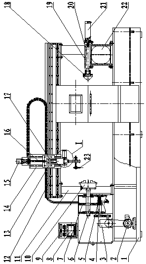
[0010] as attached figure 1 As shown, frequency conversion motor 2, speed reducer 3, gantry 11, and tailstock 22 are fixed on the designated position of frame 1; Before work, first set the welding voltage, current, air pressure control, number of welding circles of each layer of the workpiece to be welded by the encoder, the frequency conversion motor 2 drives the peripheral welding speed of the workpiece to be welded, and the stepper motor 15 drives the automatic lifting of the welding torch between layers. The stepper motor 25 drives the swing speed and amplitude of the swing device, and the cylinder 21 pushes and pulls the data program for the tightening and loosening of the weldment, and inputs it in the PLC programmable controller 9; clamps on the three-jaw chuck 10 The workpiece to be welded and click on the tightening program of the cylinder 21 in the touch screen 8, so that the axis of the workpiece to be welded is placed on the line connecting the axis of the three-ja...


PUM


Abstract

The invention relates to a gantry type programmable control girth welding machine, which comprises an automatic control system, a transmission system, a jacking mechanism and a welding gun movement control mechanism, wherein the welding gun movement control mechanism comprises a transverse displacement device, a longitudinal lifting device and a swinging device. In the transmission system, a transmission shaft is provided with a spline and a spline gear, so a main shaft and the transmission system are engaged or disengaged, to manually rotate the welding piece without load. In the working piece jacking mechanism, the welding piece is subjected to flexible compression by an air cylinder pushing jacking needle, to realize the anti-loosening purpose. In the longitudinal lifting device, a stepping motor drives a screw rod to rotate, so the welding gun is lifted to the proper place. In the swinging device, the stepping motor drives a swinging screw rod to rotate forward and reversely, so the reciprocating swinging of the welding gun head is realized, and the technical defects in the existing gantry type programmable control girth welding machine are solved. The welding machine has the advantages that the automation degree is high, the welding quality is high, the operation is convenient, the safety and the reliability are realized, and the like.

Description

technical field [0001] The invention relates to a welding machine, in particular to a welding machine for automatic welding of a V-shaped annular seam between a cylinder barrel and a cylinder body and an annular angle seam between a cylinder body and a flange, and belongs to the field of numerically controlled welding machinery manufacturing. Background technique [0002] With the wide application of numerical control technology in various machines, welding machines are also equipped with numerical control systems to implement precise control of workpiece clamping, transmission, welding torch position, welding start and end, etc. through numerical control programs. Practice has proved that the effect is Very good, its advantages such as uniform welding, good penetration, smooth welding surface and high welding efficiency are obvious. However, as a whole machine, the numerical control system is only a command system, so it is far from enough to have the numerical control syst...

Claims


Application Information

Patent Timeline
Patent Type & Authority Applications(China)
IPC IPC(8): B23K37/00B23K37/02B23K37/04
CPCB23K37/0252B23K37/0247B23K37/0435B23K37/047
Inventor 沈浩
Owner 沈浩
Why Eureka
Try Eureka