
High thermal conductivity and high voltage resistance power cable sleeve

A power cable and high-voltage-resistant technology, which is applied in the field of high-thermal-conduction and high-voltage-resistant power cable casings, can solve problems that affect the service life of power cables, reduce the current carrying capacity of power cables, and increase the temperature of power cables, and overcome the strength difference. , avoid the effect of temperature rise, toughness and heat resistance improvement

Active Publication Date: 2014-02-19
福建恒杰塑业新材料有限公司
View PDF3 Cites 2 Cited by
  • Summary
  • Abstract
  • Description
  • Claims
  • Application Information

AI Technical Summary

Problems solved by technology

The main problem of using HDPE pipes and MPP pipes as power cable casings is that the power cables will generate heat during normal operation, which will increase the temperature of the power cables. However, due to the poor thermal conductivity of plastic casings, it is difficult to transfer heat to the In the soil, the temperature of the power cable is further increased, thereby reducing the current carrying capacity of the power cable and seriously affecting the service life of the power cable

Method used


Image

  • High thermal conductivity and high voltage resistance power cable sleeve
  • High thermal conductivity and high voltage resistance power cable sleeve
  • High thermal conductivity and high voltage resistance power cable sleeve

Examples


Embodiment 1

[0030] 1. The parts by weight are polyethylene: 85-95 parts, nano-scale copper powder: 3-15 parts, zinc oxide: 3-5 parts, polypropylene grafted maleic anhydride: 3-5 parts;

[0031] 2. Process the above mixed materials by extrusion, molding or injection;

[0032] 3. Cooling and molding the pipe obtained by the extrusion, molding or injection method to obtain a high thermal conductivity and high voltage resistant power cable sleeve.

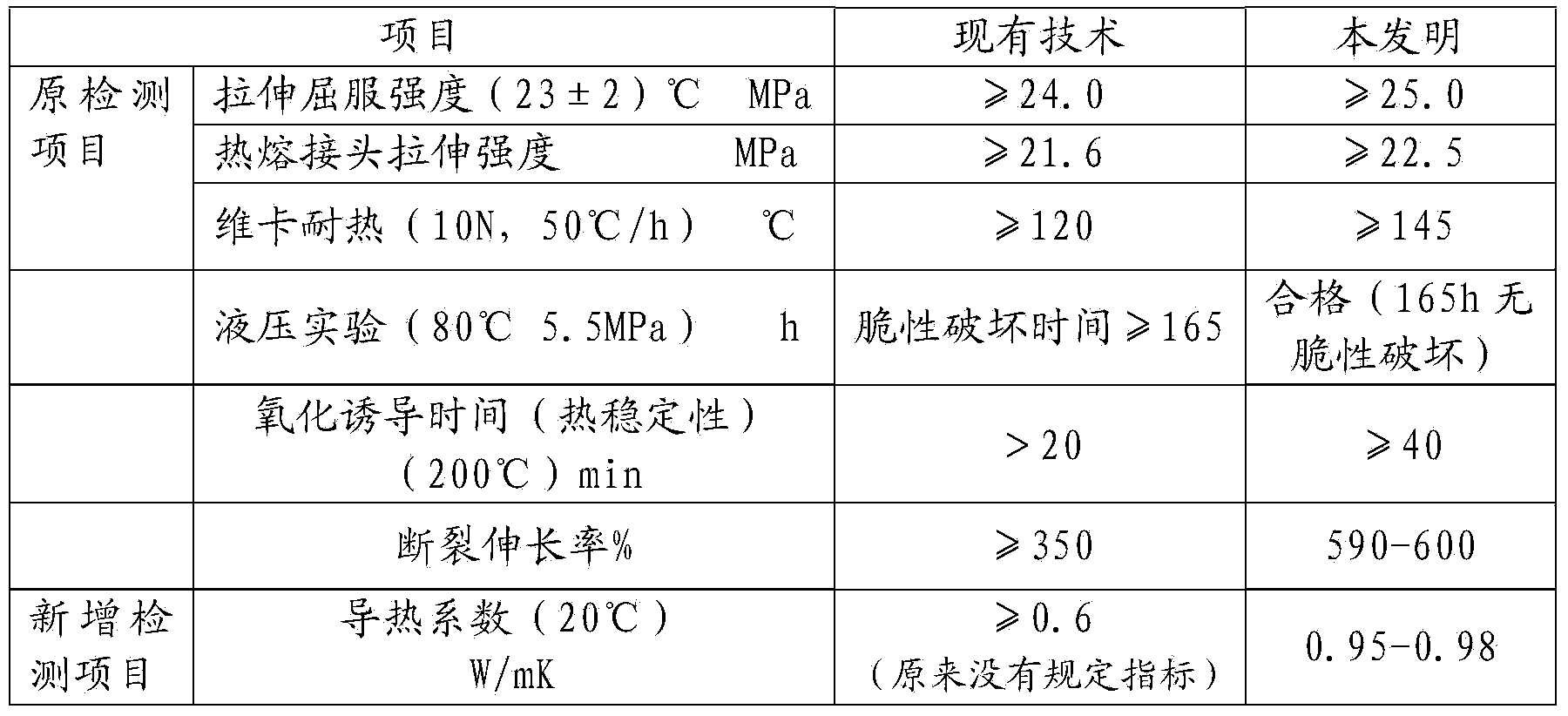
[0033] The main performance index of this embodiment is compared with existing standard as follows:

[0034]

Embodiment 2

[0036] 1. The parts by weight are polyethylene: 85-95 parts, nanoscale copper-aluminum mixed powder: 3-15 parts, mixture of barium carbonate, chromium carbonate and silicon dioxide: 3-5 parts, polypropylene grafted with Malay Anhydride: 3 to 5 parts mixed;

[0037] 2. Process the above mixed materials by extrusion, molding or injection;

[0038] 3. Cooling and molding the pipe obtained by the extrusion, molding or injection method to obtain a high thermal conductivity and high voltage resistant power cable sleeve.

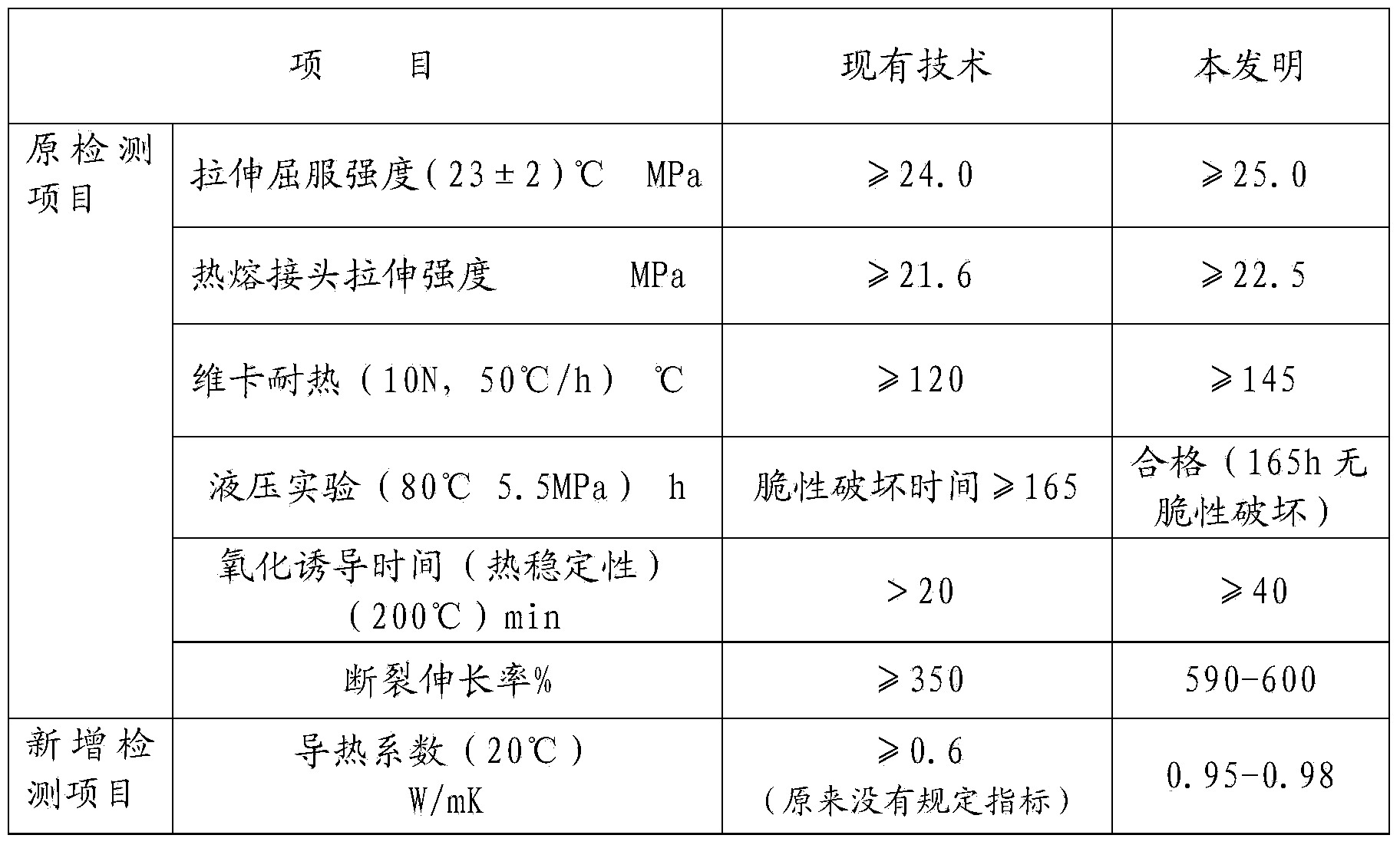
[0039] The main performance index of this embodiment is compared with existing standard as follows:

[0040]

Embodiment 3

[0042] 1. The parts by weight are polypropylene: 85-95 parts, nano-scale copper-iron mixed powder: 3-15 parts, montmorillonite: 3-5 parts, polypropylene grafted maleic anhydride: 3-5 parts;

[0043] 2. Process the above mixed materials by extrusion, molding or injection;

[0044] 3. Cooling and molding the pipe obtained by the extrusion, molding or injection method to obtain a high thermal conductivity and high voltage resistant power cable sleeve.

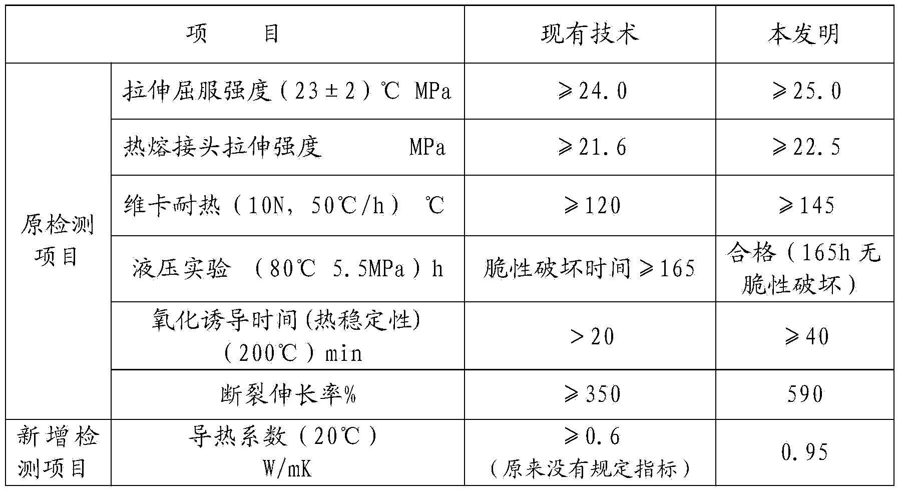
[0045] The main performance index of this embodiment is compared with existing standard as follows:

[0046]


PUM


Abstract

The invention relates to a high thermal conductivity and high voltage resistance power cable sleeve. A preparation method of the sleeve comprises the following components in parts by weight: 85-95 parts of polyolefin, 3-15 parts of heat conduction metal assistant, 3-5 parts of rigidity and roughness improvement assistant, and 3-5 parts of compatilizer. Through adding a certain ratio of nanometer-level heat conduction metal assistant in the preparation material, the power cable sleeve has excellent heat conduction performance for quickly and efficiently transferring heat generated by operating power cables to prevent the temperature increment of the power cables, so that stable carrying capability of the power cables is guaranteed, the service life of the power cables is prolonged, and the strength, the roughness and the heat resistance of the power cable sleeve are largely improved; and the power cable sleeve overcomes the bottleneck problems of the conventional sleeves such as weak strength, weak roughness, low heat resistance grade and weak heat conduction performance.

Description

technical field [0001] The invention relates to the technical field of power cables, in particular to a high thermal conductivity and high voltage resistant power cable casing. Background technique [0002] With the continuous development of society and economy, the scale of construction is increasing day by day, especially the urban infrastructure construction, environmental protection facilities and residential construction are growing rapidly, and many urban power cables are required to be grounded. [0003] There are more and more construction methods for power cable conduits using non-excavation towing pipes. The pipes mainly include HDPE pipes and MPP pipes. The main problem of using HDPE pipes and MPP pipes as power cable casings is that the power cables will generate heat during normal operation, which will increase the temperature of the power cables. However, due to the poor thermal conductivity of plastic casings, it is difficult to transfer heat to the In the so...

Claims


Application Information

Patent Timeline
Patent Type & Authority Applications(China)
IPC IPC(8): C08L23/06C08L23/12C08L23/20C08L51/06C08K13/02C08K3/08C08K3/22C08K3/26C08K3/36C08K3/34C08K5/098C08K5/13H01B3/44
CPCC08K2201/011C08L23/06C08L23/12C08L23/20C08L2201/08C08L2203/18C08L2203/20H01B3/441C08L51/06C08K2003/085C08K2003/2296C08K2003/0812C08K2003/265C08K3/26C08K3/36C08K2003/0856C08K3/346C08K5/098C08K13/02
Inventor 林真源许建钦
Owner 福建恒杰塑业新材料有限公司
Learn More