
On-line control method of banded structure and hardness of gear steel and post-rolling on-line controlled cooling bed device

A banded structure and control method technology, applied in the direction of cooling bed, heat treatment process control, metal rolling, etc., can solve the problems of increasing the difficulty of cutting gear steel, reducing the service life of tools, unstable structure and performance, etc., to achieve applicability Strong, improve production efficiency, improve the effect of product quality

Inactive Publication Date: 2014-02-19
SHANGHAI UNIV
View PDF4 Cites 12 Cited by
  • Summary
  • Abstract
  • Description
  • Claims
  • Application Information

AI Technical Summary

Problems solved by technology

However, for Cr-Mo and Cr-Ni-Mo series of gear steels with high hardenability, it is easy to obtain bainite structure, resulting in high hardness, which increases the difficulty of cutting gear steel and reduces the service life of tools.
The best cutting hardness range of gear steel is 160-230HB. The current cooling control of the bar after rolling is insufficient, the summer cooling speed is slow and the band structure is serious, and the winter cooling speed is fast. The production process is difficult to meet the production requirements of high-quality gear steel grades. Generally, the strip grade of gear steel can only be controlled at about 2.5 using the traditional post-rolling cooling bed air-cooling process. See Figure 5 , it can be seen from the microscopic metallographic photos that the belt-like tendency of the gear steel is still relatively obvious

Method used


Image

  • On-line control method of banded structure and hardness of gear steel and post-rolling on-line controlled cooling bed device
  • On-line control method of banded structure and hardness of gear steel and post-rolling on-line controlled cooling bed device
  • On-line control method of banded structure and hardness of gear steel and post-rolling on-line controlled cooling bed device

Examples


Embodiment 1

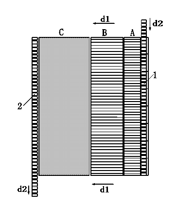
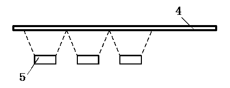
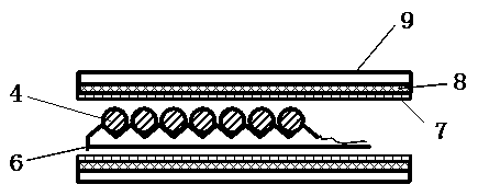
[0029] In this example, see Figure 1 ~ Figure 4, an on-line controlled cooling and cooling bed device after rolling, which is composed of an input roller table 1, a cooling bed system, an output roller table 2 and a control system, and the control system is connected to a series of temperature sensor output terminals of the cooling bed system. , the temperature sensor respectively detects the initial cooling temperature of the gear steel bar 4 entering the cooling bed system and the final cooling temperature leaving the cooling bed system, the command signal output end of the control system and the rolling material conveying mechanism of the cooling bed system, and then controls the gear steel bar The cooling speed and cooling residence time of material 4 are characterized in that: the cooling bed system is composed of pre-cooling cooling bed A, air-cooling cooling bed B and slow cooling cooling bed C three-section step-by-step cooling bed in sequence, and the pre-cooling cool...

Embodiment 2

[0034] This embodiment is basically the same as Embodiment 1, especially in that:

[0035] In this example, AISI 8620H (20CrNiMo) gear steel is selected, the specification of the continuous casting slab is 300mm×300mm, the diameter of the gear steel bar 4 after final rolling is φ120mm, and the surface temperature is 930~970°C. 1 Arrive at the pre-cooling cooling bed A, pre-cooling on the pre-cooling cooling bed A for 160~170s, the surface temperature of the gear steel bar 4 reaches 800~830°C, the temperature sensor on the pre-cooling cooling bed A receives the signal, and the control system passes the pre-cooling The moving gear rack stepping mechanism of cooling bed A transports the gear steel bar 4 to air-cooling cooling bed B. The axial flow fan 5 performs forced air cooling on the gear steel bar 4, and the gear steel bar 4 quickly passes through the α+γ two-phase region on the Fe-C phase diagram, effectively suppressing the pro-eutectoid ferrite along the rolling direction...

Embodiment 3

[0037] This embodiment is basically the same as the previous embodiment, and the special features are:

[0038] In this example, Cr-Mo series SCM822H (22CrMoH) gear steel is selected, the specification of the continuous casting slab is 300mm×340mm, the diameter of the gear steel bar 4 after final rolling is φ90mm, and the surface temperature is 930~980°C. The output roller table 1 reaches the pre-cooling cooling bed A, and pre-cools on the pre-cooling cooling bed A for 130~150s. The surface temperature of the gear steel bar 4 is 800~830°C. The feeding mechanism transports the rods to the air-cooled cooling bed B. The axial flow fan 5 performs forced air cooling on the gear steel bar 4, and the gear steel bar 4 quickly passes through the α+γ two-phase region on the Fe-C phase diagram, effectively suppressing the pro-eutectoid ferrite along the rolling direction Band-shaped precipitation, air cooling for about 400s. The surface temperature of the gear steel bar 4 is 660°C, whic...


PUM

PropertyMeasurementUnit
diameteraaaaaaaaaa
diameteraaaaaaaaaa

Abstract

The invention discloses an on-line control method of a banded structure and hardness of gear steel. The method comprises the steps: controlling the finishing temperature of a gear steel rod at 900-980 DEG C, controlling the cooling speed of the gear steel rod in a three-stage cooling manner after rolling: air-cooling the high temperature gear steel rod after the rolling, reducing the surface temperature of the rod to 800-830 DEG C, and controlling the difference between the core temperature and the surface temperature of the rod to be within 150 DEG C, performing forced air cooling on the precooled rod, controlling the surface temperature of the rod, air-cooling to 620-680 DEG C, keeping the rod after the forced cooling warm, slowly cooling, and stopping cooling for 15-50min. The invention further discloses a post-rolling on-line controlled cooling bed device. A cooling bed system of the device is formed by combining three stepped cooling beds, namely a precooling bed, an air cooling bed and a slow cooling bed. The method can control the banded structure within a second stage, the structural homogeneity of the gear steel rod is improved, and the hardness requirements during blanking of the gear steel rod are met.

Description

technical field [0001] The invention relates to a gear steel material production process and a device thereof, in particular to a post-rolling heat treatment method of a wheel steel rolled material and a device thereof, which are applied in the field of gear steel product manufacturing. Background technique [0002] Gear steel is a key material for the manufacture of transmission parts such as automobile gearboxes and rear axles, and has high requirements for various metallurgical indicators including banded structures. The banded structure in gear steel refers to the structure formed along the rolling direction, and the bands dominated by proeutectoid ferrite and bands dominated by pearlite are stacked on each other, which is an internal defect of the steel. The existence of banded structure will make the mechanical properties of steel anisotropic, and the properties along the banded direction are better than its transverse properties, that is, the plasticity, impact toughn...

Claims


Application Information

Patent Timeline
Patent Type & Authority Applications(China)
IPC IPC(8): C21D8/02B21B43/00C21D1/84C21D11/00
Inventor 闵永安欧阳剑雄杨超邵光杰付金明曹红福孙鸿平张剑峰
Owner SHANGHAI UNIV
Learn More