A demodulation method of multi-channel fiber grating absolute wavelength demodulation system based on single detector

A fiber grating and single detector technology, applied in the field of demodulation of multi-channel fiber grating absolute wavelength demodulation system, can solve the problems of increasing system complexity, reducing demodulation accuracy, wavelength measurement error, etc., to achieve absolute wavelength measurement , the effect of improving demodulation accuracy and eliminating measurement errors

Inactive Publication Date: 2016-01-13
TSINGHUA UNIV
View PDF8 Cites 3 Cited by
  • Summary
  • Abstract
  • Description
  • Claims
  • Application Information

AI Technical Summary

Problems solved by technology

The separate setting of the reference optical path and the sensing optical path increases the complexity of the system, and the sensing optical path of each channel needs to be equipped with a detector, and the number of detectors is too large
In addition, when used for long-distance sensing, the sensing fiber grating is often far away from the frequency-sweeping light source, so the transmission fiber is long, so the long transmission time will be superimposed on the final demodulation result, resulting in wavelength measurement error
At the same time, when the swept light is transmitted in the long-distance optical fiber, nonlinearity and dispersion will be introduced, which will reduce the demodulation accuracy

Method used


Image

  • A demodulation method of multi-channel fiber grating absolute wavelength demodulation system based on single detector
  • A demodulation method of multi-channel fiber grating absolute wavelength demodulation system based on single detector
  • A demodulation method of multi-channel fiber grating absolute wavelength demodulation system based on single detector

Examples


Embodiment Construction

[0031] The implementation of the present invention will be described in detail below in conjunction with the drawings and examples.

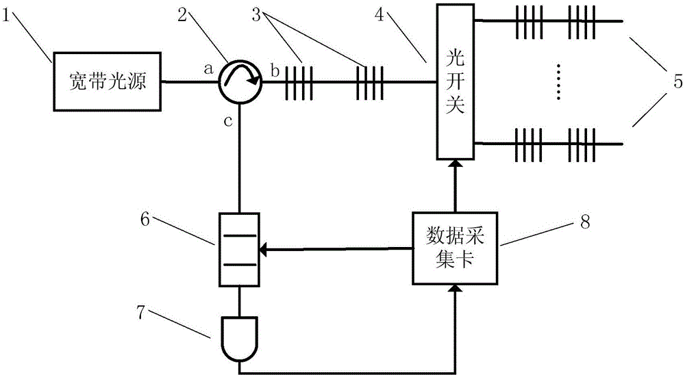
[0032] like figure 1 As shown, the broadband light source 1 is a light source with an output pigtail, and its output light passes through the circulator 2 and is reflected by two reference fiber gratings 3 connected in series. The reflected light is composed of two narrow-band lights, and the center of the narrow-band light The wavelengths correspond to the central wavelength l of the two reference fiber gratings 3, respectively ref1 and l ref2 , the reflected light enters the tunable filter 6 through the b port and the c port of the circulator 2 in sequence. The transmitted light of the broadband light source 1 passing through the reference fiber grating 3 reaches the corresponding channel where the sensor fiber grating 5 is located through the 1×N optical switch 4 (N=4), wherein the data acquisition card 8 generates a strobe signal to strobe...


PUM


Abstract

A multi-channel fiber bragg grating absolute wavelength demodulation system based on a single detector comprises a broadband light source, a circulator, reference fiber bragg gratings, a 1*N optical switch, N-path sensing fiber bragg grating arrays, a tunable filter, a photoelectric detector and a data acquisition card. The invention simultaneously provides a demodulation method based on the system. The method is characterized in that the broadband light source generates light; the light passes through the circulator, then passes through the two reference fiber Bragg gratings and then is divided into transmission light and reflected light; the transmission light enters into the 1*N optical switch; a gating signal generated by the data acquisition card makes the light enter into a corresponding sensing fiber bragg grating channel; the reflected light enters into the tunable filter via the circulator; reflected light of a sensing fiber bragg grating also enters into the tunable filter via the circulator; frequency sweeping light is received by the photoelectric detector; a spectrum signal is converted into a time domain signal; then demodulation is performed so that a relative position of the reference fiber bragg gratings and the sensing fiber bragg grating is acquired. By using the system and the method of the invention, the system structure can be simplified and a wavelength measurement error caused by optical fiber transmission is eliminated.

Description

technical field [0001] The invention belongs to the technical field of optical fiber sensing, and in particular relates to a demodulation method of a multi-channel fiber grating absolute wavelength demodulation system based on a single detector. Background technique [0002] With the rapid development of optical fiber communication technology, fiber Bragg grating sensor has received more and more attention as a new sensor device for strain and temperature sensing. Compared with traditional electrical and optical strain sensors, fiber gratings have unique advantages, such as high sensitivity, no electromagnetic interference because the sensing signal is wavelength coded, easy to reuse and quasi-distributed sensing, and are currently used in civilian structures , aerospace, shipping, petrochemical and medical fields have been widely used. In order to demodulate the wavelength change of fiber gratings, many demodulation schemes have been proposed, such as: matched grating filt...

Claims


Application Information

Patent Timeline
Patent Type & Authority Patents(China)
IPC IPC(8): G01D5/26G02F2/00
Inventor 杨昌喜梅佳伟
Owner TSINGHUA UNIV
Why Eureka
Try Eureka