Distributed fiber Raman amplifier

A technology of Raman amplifier and distributed optical fiber, which is applied in optics, instruments, nonlinear optics, etc., can solve the problems of large Rayleigh noise, and achieve long all-optical relay distance, low Raman amplification effect, and low noise Effect

Inactive Publication Date: 2014-02-26
NO 34 RES INST OF CHINA ELECTRONICS TECH GRP
View PDF4 Cites 5 Cited by
  • Summary
  • Abstract
  • Description
  • Claims
  • Application Information

AI Technical Summary

Problems solved by technology

[0003] In order to overcome the shortcoming of excessive Rayleigh noise in the high switching gain state of the current distributed fiber Raman amplifier, the present invention provides a distributed fiber Raman amplifier that can suppress Rayleigh noise

Method used


Image

  • Distributed fiber Raman amplifier
  • Distributed fiber Raman amplifier

Examples


Embodiment 1

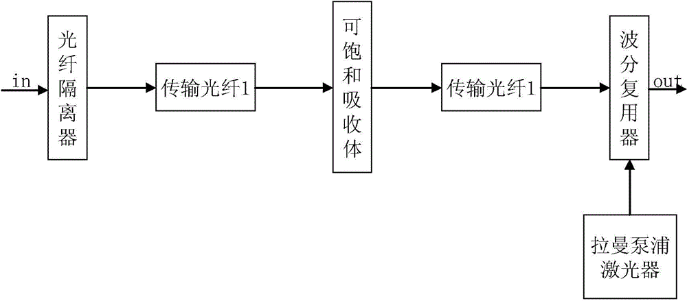
[0019] Embodiment 1 of this distributed optical fiber Raman amplifier is as figure 1 As shown, it is a distributed fiber Raman amplifier with backward pumping. The optical signal enters the transmission fiber after passing through the fiber isolator, and the end of the transmission fiber is connected to the input end of the wavelength division multiplexer. The terminal is connected to the output terminal of the Raman pump laser. A saturable absorber is inserted in the center of the transmission fiber, and the transmission fiber connecting the fiber isolator and the wavelength division multiplexer is divided into two sections of transmission fiber with equal length by the saturable absorber. The common end of the wavelength division multiplexer is the output end of the distributed optical fiber Raman amplifier, which can be connected to the communication optical fiber.

[0020] The optical fiber isolator matches the working wavelength and output power of the optical fiber ampl...

Embodiment 2

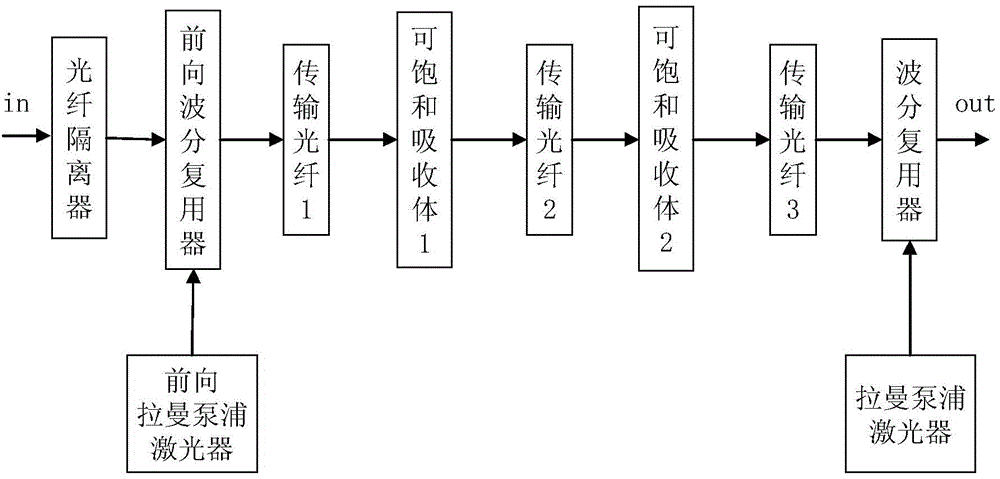
[0025] Embodiment 2 of this distributed optical fiber Raman amplifier is as figure 2 As shown, it is a distributed optical fiber Raman amplifier with bidirectional pumping. The optical signal enters the input end of the forward wavelength division multiplexer after passing through the optical fiber isolator, and the output end of the forward Raman pump laser is connected to the forward wavelength division multiplexer. The pump signal input end of the device, the pump laser light enters the forward wavelength division multiplexer, the common end of the forward wavelength division multiplexer is connected to the front end of the transmission fiber, and the forward wavelength division multiplexer couples the Raman pump light and the optical fiber The signals enter the transmission fiber together, and the optical signal is simultaneously amplified by Raman during transmission; a saturable absorber 1 and a saturable absorber 2 are inserted in the transmission fiber, and the transmi...


PUM


Abstract

The invention relates to a distributed fiber Raman amplifier. A light signal enters a transmission fiber through a fiber isolator, a tail end of the transmission fiber is connected with an input end of a wavelength division multiplexer, a pump signal input end of the wavelength division multiplexer is connected with a Raman pump laser device. Output of a signal public end of the wavelength division multiplexer is output of the distributed fiber Raman amplifier, and an amplified light signal is outputted. The transmission fiber of the distributed fiber Raman amplifier is inserted with one or two saturable absorbers for inhibiting Rayleigh noise. The absorber can be a semiconductor saturable absorber or a carbon nanotube saturable absorber. Length of the transmission fiber divided into two segments is about one half of a total length when one saturable absorber is inserted, length of the transmission fiber divided into three segments is about one third of the total length when two saturable absorbers are inserted. The distributed fiber Raman amplifier can further be a bidirectional pump distributed fiber Raman amplifier. The distributed fiber Raman amplifier effectively inhibits gain of the Rayleigh noise, realizes Raman amplification with high gain and low noise and improves an all-optical relay distance of fiber communication.

Description

technical field [0001] The invention relates to an optical fiber amplifier, in particular to a distributed optical fiber Raman amplifier applied to optical fiber communication relay amplification. Background technique [0002] The distributed fiber Raman amplifier has a very low noise figure, and the optical signal-to-noise ratio (OSNR) of the distributed fiber Raman amplifier in the fiber optic communication link is 4dB-5dB higher than that of the erbium-doped fiber amplifier (EDFA), so it can Greatly extend the maximum transmission distance of non-electric regenerative relay, or be more suitable for higher rate optical signal relay amplification. However, when the switching gain of the fiber Raman amplifier is high, the level of double Rayleigh scattering noise (DRB, hereinafter referred to as Rayleigh noise) of the Raman amplifier will exceed the level of spontaneous emission noise (ASE) and become the main noise source. Seriously affect the communication signal quality....

Claims


Application Information

Patent Timeline
Patent Type & Authority Applications(China)
IPC IPC(8): H01S3/067G02F1/39H04B10/291
Inventor 岳耀笠阳华吴国锋刘志强覃波吕宏伟欧阳竑李文甫
Owner NO 34 RES INST OF CHINA ELECTRONICS TECH GRP
Why Eureka
Try Eureka