Heat protection method for injection support plate of scramjet engine by utilizing sweat and impingement cooling

An injection support plate and engine technology, which is applied in the combustion method, combustion chamber, combustion equipment and other directions, can solve the problem of difficult to achieve effective mixing of fuel and high-speed mainstream, affecting fuel ignition and combustion, injection support plate ablation damage, etc. problems, to achieve the effect of reducing temperature, preventing ablation damage, and making up for weakened strength

Active Publication Date: 2014-03-05
TSINGHUA UNIV
View PDF6 Cites 17 Cited by
  • Summary
  • Abstract
  • Description
  • Claims
  • Application Information

AI Technical Summary

Problems solved by technology

Since the residence time of the fuel in the combustion chamber is only a few milliseconds, the traditional way of injecting fuel on the wall of the combustion chamber has the disadvantage of short penetration distance, which makes it difficult to achieve effective mixing between the fuel and the high-speed mainstream, which affects the ignition and combustion of the fuel.
[0003] The injection branch plate structure is a common device in the combustion chamber to realize the effective mixing of fuel and high-speed mainstream. The fuel is injected from the injection hole on the injection branch plate and mixed with the high-speed main flow to overcome the incident penetration The disadvan

Method used


Image

  • Heat protection method for injection support plate of scramjet engine by utilizing sweat and impingement cooling
  • Heat protection method for injection support plate of scramjet engine by utilizing sweat and impingement cooling
  • Heat protection method for injection support plate of scramjet engine by utilizing sweat and impingement cooling

Examples


Embodiment Construction

[0017] The present invention will be described in detail below in conjunction with the accompanying drawings and embodiments.

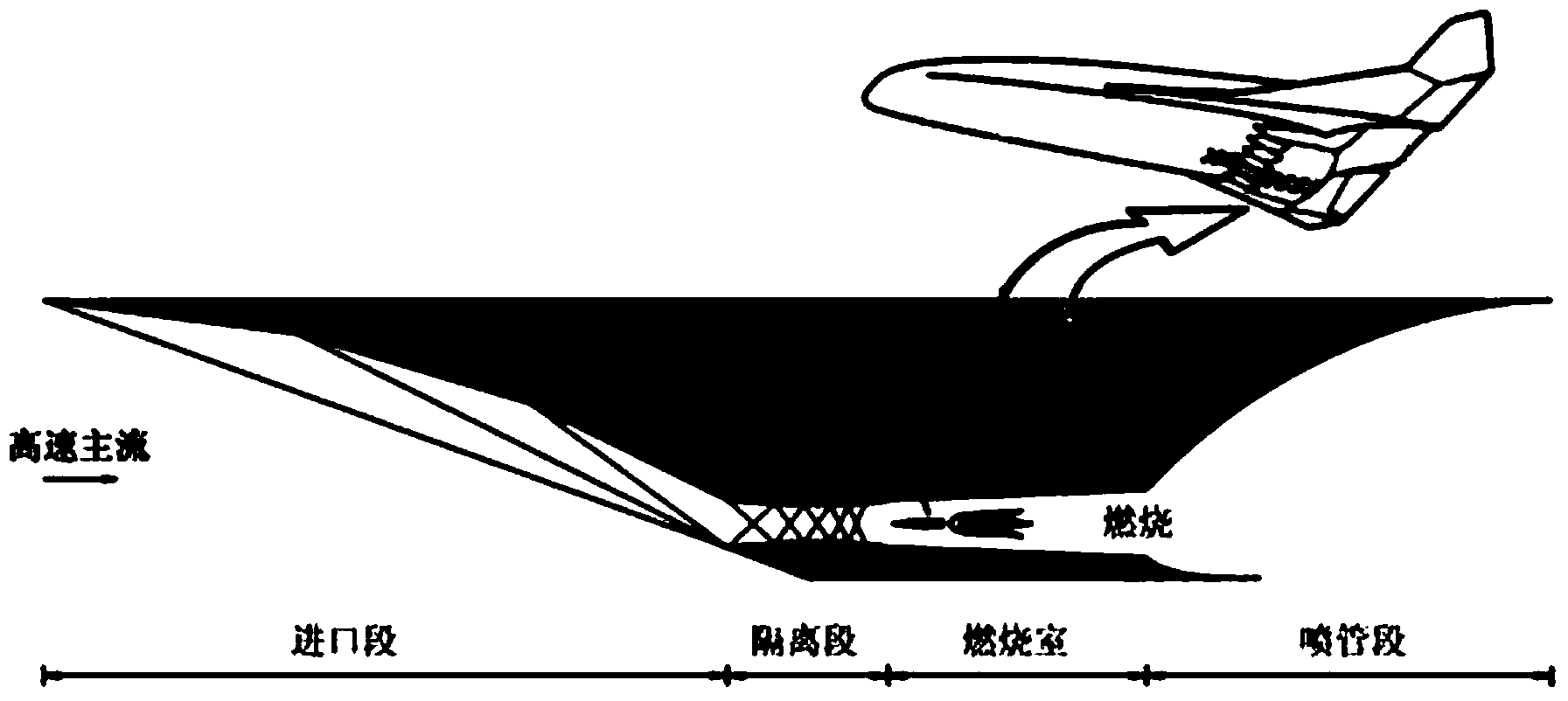
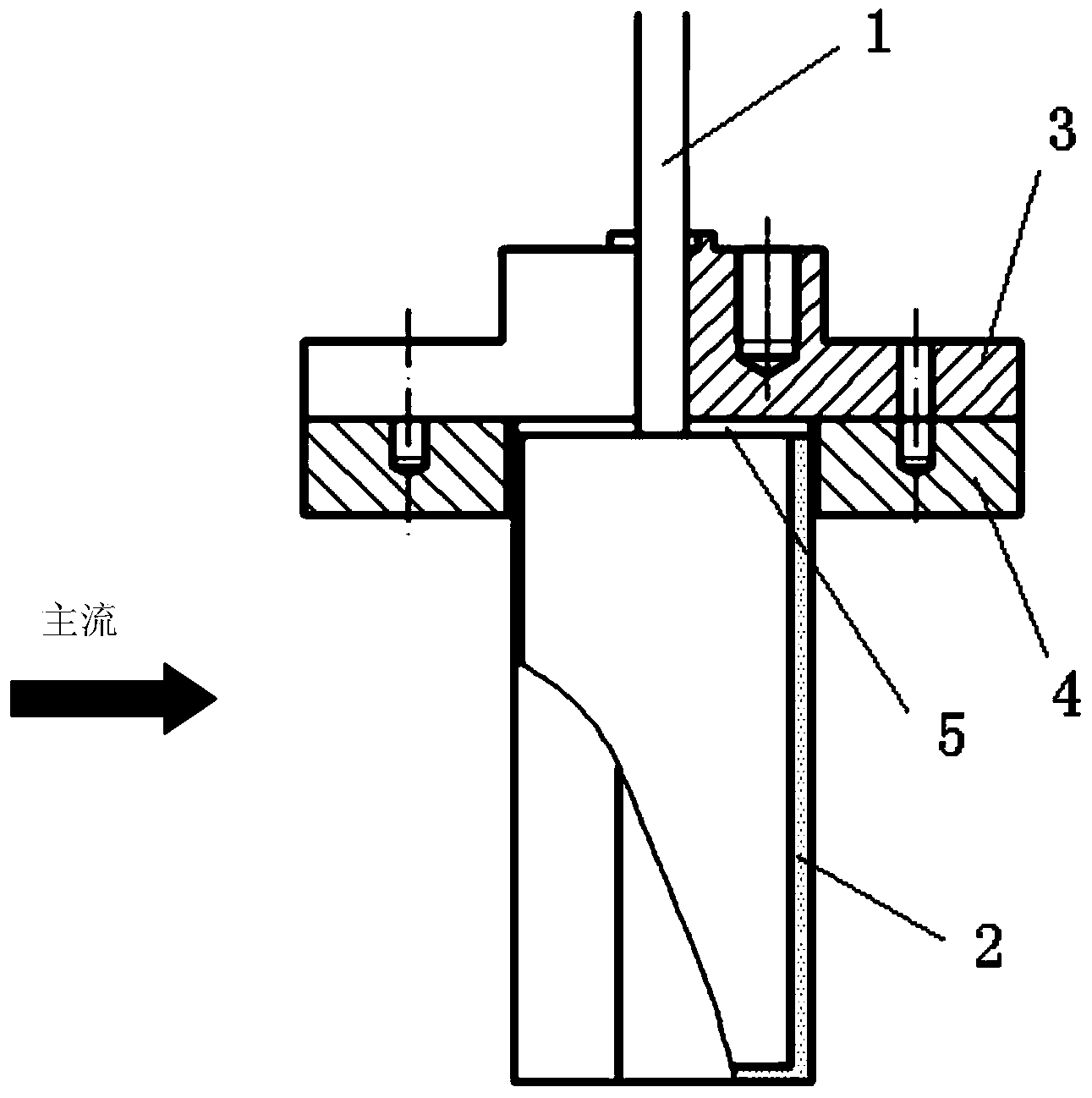
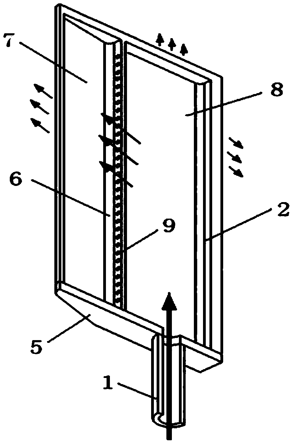
[0018] Such as figure 1 , figure 2 As shown, in a scram engine, aviation kerosene or liquid hydrogen is generally selected as fuel according to different flight Mach number ranges of the aircraft, and gaseous fuel is also used in some special working environments. The fuel is controlled by the pump carried by the scram engine itself and the valve set on the fuel channel. After reaching a certain pressure, it enters the injection branch plate 2 through a fuel pipe 1, and is set from the injection branch plate 2 according to the design requirements. It is sprayed out from the fuel injection hole, mixed with the mainstream of high-temperature and high-speed airflow, and then burned to provide power. The structure of the method of the present invention is basically the same as that of the prior art, and the difference is that the present invention impr...


PUM


Abstract

The invention relates to a heat protection method for an injection support plate of a scramjet engine by utilizing sweat and impingement cooling. The method includes the following steps that (1) a high-temperature-resistant material is used for making the injection support plate of a microporous structure, a supporting rib is arranged in the injection support plate and partitions the same into a front cavity and a rear cavity, impingement pores communicated with the front and rear cavities are formed in the supporting rib, and a fuel pipe of the scramjet engine is communicated with the rear cavity of the injection support plate; (2) by the process that fuel seeps out of pores of the injection support plate of the microporous structure, convection heat transfer is carried out forcedly to remove heat on the surface of the injection support plate, and the fuel seeps out of the surface of the injection support plate to form a film layer so as to block heat transfer of the mainstream to the injection support plate; (3) the fuel is injected from the rear cavity to the inner surface of the front cavity via the impingement pores in the supporting rib so as to perform convection heat transfer with the inner surface of the front cavity, and strength of the injection support plate is enhanced by the aid of the supporting rib in the injection support plate. Heat protection effect on the injection support plate is realized by combining the concept of impingement cooling and utilizing the fuel as a cooling agent according to porous medium characteristics, and the method can be widely applied to heat protection of injection support plates of scramjet engines in various Mach working ranges.

Description

technical field [0001] The invention relates to a thermal protection method for a high-temperature wall surface, in particular to a thermal protection method for an injection support plate of a super-combustion engine by sweating and impact cooling in a high-temperature and high-speed airflow. Background technique [0002] A scramjet is a ramjet in which fuel is burned in a supersonic airflow. When hydrocarbon fuel is used, the flight Mach number of the scramjet engine is usually below 8, and when liquid hydrogen fuel is used, the flight Mach number can reach 6-25. Such as figure 1 As shown, the supersonic or hypersonic air flow decelerates to a lower supersonic speed in the inlet section and the isolation section and enters the combustion chamber. The gas is discharged through the expansion nozzle section. Since the residence time of the fuel in the combustion chamber is only a few milliseconds, the traditional way of injecting fuel on the wall of the combustion chamber ...

Claims


Application Information

Patent Timeline
IPC IPC(8): F23R3/28
Inventor 姜培学黄拯祝银海熊宴斌
Owner TSINGHUA UNIV
Why Eureka
Try Eureka