Surgical robot passive joint based on motor drive locking

A surgical, motor-driven technology, applied in the fields of surgery, manipulators, medical science, etc., can solve the problems of complex design of hydraulically driven locking joints, difficult for medical robots, and easy leakage of hydraulic oil, which is conducive to robot system integration and easy maintenance. , to avoid the effect of easy leakage

Inactive Publication Date: 2014-03-12
HARBIN INST OF TECH
View PDF4 Cites 17 Cited by
  • Summary
  • Abstract
  • Description
  • Claims
  • Application Information

AI Technical Summary

Problems solved by technology

[0003] The purpose of the present invention is to solve the complex design of the existing hydraulically driven locking joint, which requires a hydraulic pump station and the hydraulic oil is easy to leak and is not easy to apply to medical robots; the design of the pneumatically driven locking joint requires an air pump, and the noise generated during the working process is large; The electromagnetic power locking method has the problems of high heat generation, strong electromagnetic interference, and large joint volume

Method used


Image

  • Surgical robot passive joint based on motor drive locking
  • Surgical robot passive joint based on motor drive locking

Examples


specific Embodiment approach 1

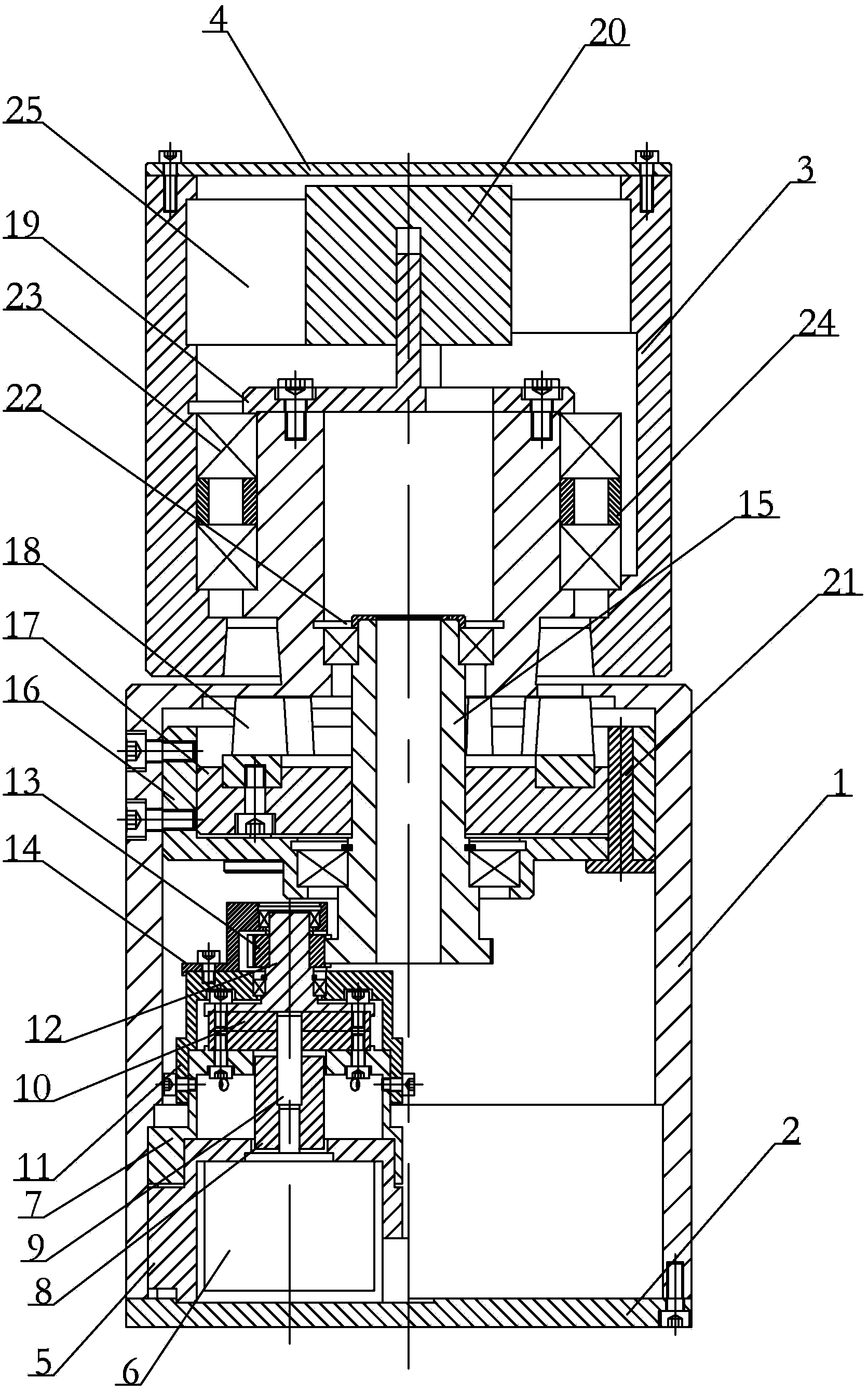
[0014] Specific implementation mode one: combine figure 1 Describe this embodiment, this embodiment includes a lower casing 1, a bottom plate 2, an upper casing 3, a top cover 4, a motor base 5, a stepping motor 6, a casing connector 7, an elastic coupling 8, and an input shaft 9 , Harmonic reducer 10, lower bearing housing 11, output shaft 12, gear 13, upper bearing housing 14, gear screw shaft 15, guide 16, support 17, wedge-shaped friction member 18, encoder shaft 19, The encoder 20 and the encoder connector 25, the bottom plate 2 is fixedly installed on the lower end of the lower case 1, the upper end of the lower case 1 is rotatably embedded in the lower part of the upper case 3, and the top cover 4 is fixedly installed on the upper case 3 The upper end of the motor seat 5 is fixedly installed in the lower housing 1, the stepping motor 6 is arranged in the motor seat 5, and the output end of the stepping motor 6 connects with the input shaft 9, the harmonic reducer 10 and...

specific Embodiment approach 2

[0020] Specific implementation mode two: combination figure 1 The present embodiment will be described. The gear screw shaft 15 of the present embodiment is a hollow gear screw shaft. Such setting realizes the internal wiring of the joint, which is beneficial to the integration of the robot system. Other compositions and connections are the same as in the first embodiment.

specific Embodiment approach 3

[0021] Specific implementation mode three: combination figure 1 To illustrate this embodiment, the passive joint of the surgical robot in this embodiment further includes a guide pin 21 , and the guide pin 21 is vertically arranged on the guide member 16 and the support member 17 . Such setting is convenient to provide guidance for the movement of the passive joint. Other compositions and connections are the same as those in the second embodiment.


PUM


Abstract

The invention discloses a surgical robot passive joint based on motor drive locking, and relates to the surgical robot passive joint which aims at solving the problems that the current hydraulic drive locking joint has a complex design and needs a hydraulic power unit and hydraulic oil easily leaks; a pneumatic drive locking joint needs an air pump so that noises are high; according to an electromagnetic power locking mode, the calorific value is large, the electromagnetic interference is strong and the joint volume large. The surgical robot passive joint based on motor drive locking is characterized in that the upper end of a lower shell can be rotatably embedded into the lower part of an upper shell, and a stepping motor is arranged in a motor base; the output end of the stepping motor is sequentially connected with an input shaft, a harmonic reducer and an output shaft from bottom to top; an elastic coupling is sheathed on the output shaft and the input shaft of the stepping motor, and a gear is arranged on the output shaft; a shell connecting piece, a lower bearing shell and upper bearing shell are sequentially installed on the motor base from bottom to top, and a gear screw is installed in the lower shell; a wedge-shaped friction piece is installed on a support piece, and a coder is installed on a coder connecting piece. The surgical robot passive joint based on motor drive locking is used for surgical robots.

Description

technical field [0001] The invention relates to a passive joint of a surgical robot, in particular to a passive joint of a surgical robot based on motor-driven locking. Background technique [0002] The introduction of robot technology into surgical operations improves the accuracy and quality of surgical operations. In robotic surgery, doctors need to manually adjust the joints of the robot to adjust the end effector of the robot to a predetermined position, and then lock the joints of the robot to achieve stable positioning of the end effector of the robot. In robot surgery, the robot joints are required to realize continuous rotation, have joint angle feedback, and can realize reliable locking at any position. At present, the design of passive joints of surgical robots mainly adopts hydraulic drive, pneumatic drive and electromagnetic power locking. The design of the hydraulically driven locking joint is complex, requiring a hydraulic pump station and the hydraulic oil ...

Claims


Application Information

Patent Timeline
Patent Type & Authority Applications(China)
IPC IPC(8): A61B19/00B25J17/02
Inventor 潘博付宜利封海波牛国君
Owner HARBIN INST OF TECH
Why Eureka
Try Eureka