
Laser energy transfer system

A laser energy transmission and energy technology, applied in the field of laser energy transmission system, can solve the problems of low surrounding energy, low laser energy transmission conversion efficiency, high intermediate energy, etc., achieve high conversion efficiency, reduce spot energy loss, and light weight Effect

Active Publication Date: 2014-03-12
NO 513 INST THE FIFTH INST OF CHINA AEROSPACE SCI & TECH
View PDF7 Cites 10 Cited by
  • Summary
  • Abstract
  • Description
  • Claims
  • Application Information

AI Technical Summary

Problems solved by technology

The current laser energy transmission is directly emitted to the photocell by the laser. However, the laser beam is a Gaussian beam, that is, the energy in the middle is high and the energy around it is low. It is affected by the spatial distribution of the beam on the surface of the photocell, the aiming accuracy of the spot and the photocell, and the photoelectric conversion efficiency of the photocell. The conversion efficiency of existing laser energy transmission is not high

Method used


Image

  • Laser energy transfer system
  • Laser energy transfer system
  • Laser energy transfer system

Examples


Embodiment Construction

[0022] The present invention will be described in detail below with reference to the accompanying drawings and examples.

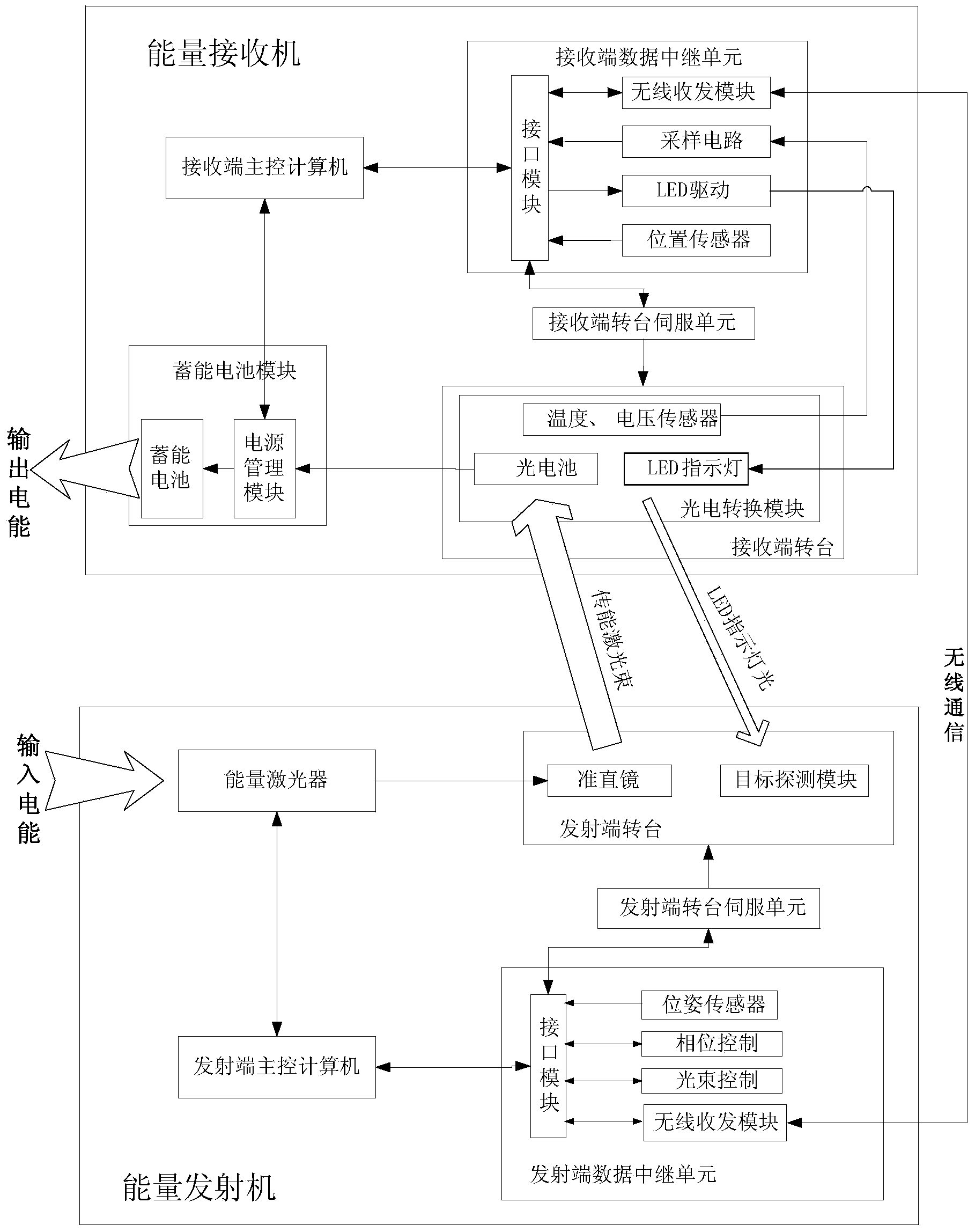
[0023] The invention provides a laser energy transmission system, such as figure 1 As shown, it is mainly composed of an energy transmitter and an energy receiver. Among them, the energy transmitter includes an energy laser, a collimating mirror, a transmitting end turntable, a transmitting end turntable servo unit, a transmitting end main control computer and a transmitting end data relay unit; an energy receiver includes a photoelectric conversion module, a receiving end turntable, a receiving end The turntable servo unit, the energy storage battery module, the main control computer of the receiving end and the data relay unit of the receiving end.

[0024] Among them, the collimating mirror is installed on the transmitting end turntable, the transmitting end turntable is connected with the transmitting end turntable servo unit, the transmitting end dat...


PUM


Abstract

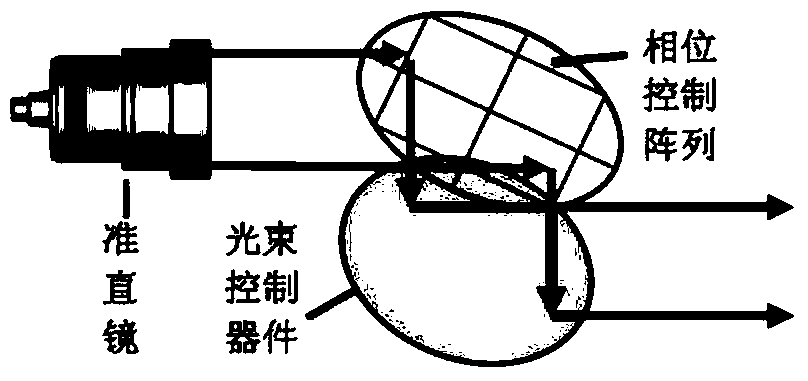
The invention discloses a laser energy transfer system. By the aid of the laser energy transfer system, pointing accuracy between an emitting end and a receiving end can be improved, uniformity of light intensity distribution of the beam receiving end can be improved, and photoelectric conversion efficiency of a photoelectric cell is improved, so that energy transfer efficiency is effectively improved. The photoelectric cell of the energy receiving end is designed, a photoelectric cell unit 1 can align to light spots in real time, high conversion efficiency is kept, a photoelectric cell unit 2 and the photoelectric cell unit 1 pass optimal power tracking constant-pressure output units prior to parallel output, loss of light spot energy at the edges of the light spots is reduced, and maximum conversion efficiency is guaranteed. Moreover, a phase control array regulates beam phases to obtain uniform light spots, pointing of beams is controlled through a beam control device, high beam pointing precision is ensured, and energy transfer efficiency of the laser energy transfer system is improved effectively.

Description

technical field [0001] The invention relates to the technical field of energy wireless transmission, in particular to a laser energy transmission system. Background technique [0002] The energy module spacecraft and mission module spacecraft of the separation module spacecraft, emergency rescue equipment in the event of geological disasters and meteorological disasters, robots performing volcanic exploration missions, and electric aircraft far away from the base without landing conditions, etc., have different working and operating environments. It has the conditions to erect cables for power supply. Laser wireless energy transmission uses laser as the medium and does not need energy transmission lines to provide energy support to the target machine working in a specific environment so that it can successfully complete the assigned tasks. It is a key means to supply energy for the above-mentioned equipment. The core indicator is the conversion efficiency of electricity to ...

Claims


Application Information

Patent Timeline
IPC IPC(8): H02S10/00H02S40/20
CPCY02E10/50
Inventor 程坤李振宇邵飞石德乐马宗峰吴世臣蔡卓燃张建德郭春辉常中坤
Owner NO 513 INST THE FIFTH INST OF CHINA AEROSPACE SCI & TECH
Learn More