Solid state heat sink device used for friction stir welding and welding method of solid state heat sink device

A friction stir welding and welding method technology, applied in the field of mechanical technology and material engineering, can solve the problems of complex supporting equipment and technical conditions, small contact area between radiator and weld, short cooling time, etc. Cooling effect, easy operation effect

Inactive Publication Date: 2014-03-19
JIANGSU UNIV OF SCI & TECH
View PDF9 Cites 22 Cited by
  • Summary
  • Abstract
  • Description
  • Claims
  • Application Information

AI Technical Summary

Problems solved by technology

[0005] Purpose of the invention: In order to overcome the deficiencies in the prior art, the present invention provides a "dry" solid-state heat sink device and method used in the friction stir welding process to achieve effective control of the weld temperature field and solve the "wet" problem. The "wet method" cooling requires complex supporting equipment and technical conditions, and the operation is more complicated, and fundamentally eliminates the defects such as weld hydrogenation and material corrosion caused by "wet" cooling
At the same time, it solves the problems of small contact area between the radiator and the welding seam and short cooling time in the general "dry" cooling, so as to obtain obvious heat dissipation effect and improve the welding quality.

Method used


Image

  • Solid state heat sink device used for friction stir welding and welding method of solid state heat sink device
  • Solid state heat sink device used for friction stir welding and welding method of solid state heat sink device
  • Solid state heat sink device used for friction stir welding and welding method of solid state heat sink device

Examples


Embodiment Construction

[0025] The present invention will be further described below in conjunction with the accompanying drawings.

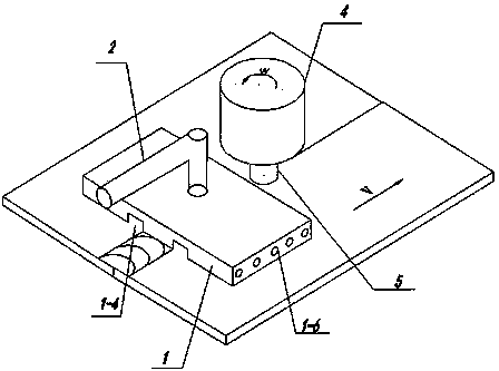
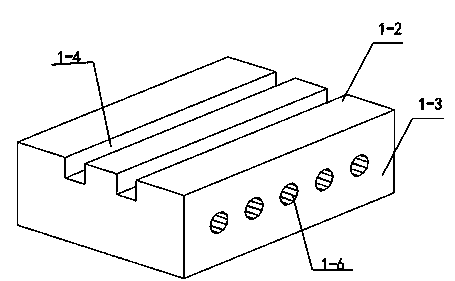
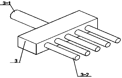
[0026] Such as Figure 1 to Figure 4 As shown, a solid heat sink device for friction stir welding of the present invention includes a solid heat sink 1, a push rod 2 connected to the solid heat sink 1 and a cooling water pipe 3, and the solid heat sink 1 includes an upper bottom surface 1-1 , the lower bottom surface 1-2 and the side surface 1-3, the lower bottom surface 1-2 is provided with a heat dissipation channel 1-4 along the welding direction, and the inside of the solid heat sink 1 is provided with a number of cooling channels 1-6 in a direction perpendicular to the welding direction , the cooling water channel 1-6 runs through the two sides 1-3, the cooling water channel 1-6 is connected with the cooling water pipe 3, the upper bottom surface 1-1 of the solid heat sink is provided with a mounting hole 1-5, and one end of the push rod 2 is located in the mounti...


PUM


Abstract

The invention discloses a solid state heat sink device used for friction stir welding and a welding method of the solid state heat sink device. The solid state heat sink device comprises a solid state heat sink, a push rod connected with the solid state heat sink and a cooling water pipe, wherein the solid state heat sink comprises an upper bottom face, a lower bottom face and a side face, heat dissipation through grooves are formed in the lower bottom face, cooling water channels are formed in the side face, the cooling water channels are connected with the cooling water pipe, and an installation hole used for installation of the push rod is formed in the upper bottom face of the solid state heat sink. The solid state heat sink device synchronously moves in the welding direction along with a friction stir welding device, and the lower bottom face makes full contact with the surface of a weldment so that heat conduction can be achieved, heat dissipation and cooling can be conducted on a weld joint which is still at a high temperature, and the peak temperature of the weld joint can be effectively lowered. Meanwhile, cooling water is injected into the water channels formed inside the heat sink to conduct forced heat dissipation and cooling. According to the solid state heat sink device and the welding method, the weld joint can be prevented from being overheated, weld joint crystalline grains are refined, the well-formed formation is improved, residual stress and strain of a welded joint can be eliminated or reduced, and the aims of improving the quality of the weld joint and improving the comprehensive performance of the joint are achieved.

Description

technical field [0001] The invention relates to a solid-state heat sink device and method for friction stir welding, which can be used for heat dissipation and cooling and quality control of friction stir welding parts, and belongs to the fields of mechanical technology and material engineering. Background technique [0002] Friction Stir Welding (FSW) is a new type of solid-phase joining technology, which overcomes the problems of welding defects such as cracks and pores in the fusion welding method, and enables some materials that were difficult to weld in the past to achieve high-quality welding. , and has irreplaceable obvious advantages in the fields of welding aluminum, magnesium and its alloys. During the friction stir welding process, the friction between the stirring head and the material to be welded generates high temperature, and the material around the stirring head enters a thermoplastic state, and diffusion and dynamic recrystallization occur under the act...

Claims


Application Information

Patent Timeline
Patent Type & Authority Applications(China)
IPC IPC(8): B23K20/12B23K20/26
CPCB23K20/1235B23K20/1245B23K37/003
Inventor 芦笙杨代立陈书锦陈静
Owner JIANGSU UNIV OF SCI & TECH
Why Eureka
Try Eureka