Thermal transfer printing conductive film for radio-frequency identification tag antenna

A technology of radio frequency identification tags and conductive films, which is applied in the direction of layered products, metal layered products, synthetic resin layered products, etc., can solve problems such as unstable conductivity, affecting antenna stability, complex process, etc., and achieve fineness High, good hot stamping adhesion effect, conductive and stable effect

Active Publication Date: 2014-03-19
BAODING LUCKY INNOVATIVE MATERIALS
View PDF4 Cites 12 Cited by
  • Summary
  • Abstract
  • Description
  • Claims
  • Application Information

AI Technical Summary

Problems solved by technology

The traditional etching/stamping manufacturing method has disadvantages such as complex process and low efficiency, especially for paper and other materials, it needs to be processed after etching
However, the conductivity stability of conductive in...

Method used


Image

  • Thermal transfer printing conductive film for radio-frequency identification tag antenna

Examples


Embodiment 1

[0036] Preparation of release layer coating solution:

[0037] Desmolux® XP2740 8.0 servings

[0038] Nano silica modified acrylate resin 15.0 parts

[0039] Dipentaerythritol hexaacrylate 30.0 parts

[0040] 184 3.0 copies

[0041] Fumed silica (particle size 1 micron) 6.5 parts

[0042] Tech-6300 1.0 copies

[0043] EFKA 3777 0.5 parts

[0044] Butanone 10.0 parts

[0045] Ethyl acetate 20.0 parts.

[0046] Add methyl ethyl ketone and ethyl acetate into the container, and then add the above-mentioned other components sequentially under stirring state, and after fully stirring and mixing, the release layer coating liquid is obtained.

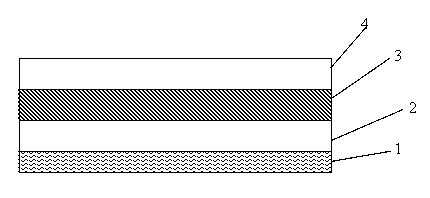
[0047] On the surface of the PET base material with a thickness of 12 microns, the above-mentioned release layer coating solution is coated, with a thickness of 3 microns, then vacuum-plated silver on the release layer, with a thickness of 150 nm, and then coated with a conductive adhesive layer with a thickness of 2 microns to obtain T...

Embodiment 2

[0050] Preparation of release layer coating solution:

[0051]Desmolux® XP2738 16.0 parts

[0052] Nano silica modified acrylate resin 10.0 parts

[0053] Dipentaerythritol hexaacrylate 20 parts

[0054] 184 1.0 copies

[0055] Fumed silica (particle size 1 micron) 3.0 parts

[0056] Tech-6300 0.6 parts

[0057] EFKA 3777 0.4 parts

[0058] Butanone 25 parts

[0059] 32 parts of ethyl acetate.

[0060] Add methyl ethyl ketone and ethyl acetate into the container, and then add the above-mentioned other components sequentially under stirring state, and after fully stirring and mixing, the release layer coating liquid is obtained.

[0061] On the surface of the PET base material with a thickness of 11 microns, apply the above-mentioned release layer coating solution with a thickness of 2 microns, then vacuum copper plating on the release layer with a thickness of 150 nm, and then coat a conductive adhesive layer with a thickness of 2 microns to obtain Thermal transfe...

Embodiment 3

[0064] Preparation of release layer coating solution:

[0065] Desmolux® XP2740 10.0 servings

[0066] Nano silica modified acrylate resin 12.0 parts

[0067] Dipentaerythritol hexaacrylate 20 parts

[0068] 1173 1.5 copies

[0069] Fumed silica (particle size 1 micron) 4.0 parts

[0070] Tech-6300 1.5 parts

[0071] EFKA 3777 0.5 parts

[0072] Butanone 25 parts

[0073] 25 parts of ethyl acetate.

[0074] Add methyl ethyl ketone and ethyl acetate into the container, and then add the above-mentioned other components sequentially under stirring state, and after fully stirring and mixing, the release layer coating liquid is obtained.

[0075] On the surface of the PET base material with a thickness of 11 microns, the above-mentioned release layer coating solution is coated, with a thickness of 2.5 microns, and then vacuum copper plating on the release layer, with a thickness of 180nm, and then coated with a thickness of 4 microns. Conductive adhesive layer, obtained...


PUM

PropertyMeasurementUnit
Thicknessaaaaaaaaaa
Thicknessaaaaaaaaaa
Thicknessaaaaaaaaaa

Abstract

The invention relates to a thermal transfer printing conductive film for a radio-frequency identification tag antenna. The conductive film comprises a base material, a release layer which is coated on the surface of the base material, a conductive metal layer which is evaporated on the surface of the release layer and a conductive adhesive layer which is coated on the surface of the conductive metal layer, wherein the release layer is formed by solidifying coating liquid consisting of the following components in parts by weight: 8 to 16 parts of ammonium-base modified acrylic ester, 10 to 15 percent of inorganic modified acrylic ester resin, 20 to 30 parts of dipentaerythritol hexaacrylate, 1 to 3 parts of photoinitiator, 3 to 7.5 parts of gas-phase silicon dioxide, 0.6 to 2 parts of dispersing agent, 0.4 to 1.5 parts of anti-adhesion agent and 30 to 57 parts of solvent. The radio-frequency identification tag antenna produced by adopting the thermal transfer printing conductive film has the advantages of high fineness and stability in conductivity.

Description

technical field [0001] The invention relates to a conductive film, in particular to a heat-transfer conductive film used for radio frequency identification tag antennas. Background technique [0002] At present, the manufacturing methods of RFID tag antennas include chemical etching / stamping antennas, printing antennas, wire-wound antennas, etc. Common RFID antenna substrates include paper base and film base. Internationally, etching / stamping antennas are currently the mainstay. With the rapid development and application of radio frequency identification cards and the development of conductive inks, the application of printed antennas is also gradually increasing. The traditional etching / stamping manufacturing method has the disadvantages of complex process and low efficiency, especially for paper and other materials, which need to be processed after etching. However, the conductive stability of conductive ink printing is greatly affected by the conductivity of the ink, and...

Claims


Application Information

Patent Timeline
IPC IPC(8): B32B15/08B32B27/18
Inventor 罗超刘彦峰
Owner BAODING LUCKY INNOVATIVE MATERIALS
Why Eureka
Try Eureka