
Catalyst regenerator and regeneration method for methanol aromatization process

A regenerator and catalyst technology, applied in the direction of catalyst regeneration/reactivation, physical/chemical process catalysts, chemical instruments and methods, etc., can solve the problems of low control temperature, less heat, wide temperature resistance range, etc., and achieve process safety. Increase, realize comprehensive utilization, prolong the effect of regeneration life

Active Publication Date: 2015-08-12
HUADIAN COAL IND GRP +1
View PDF1 Cites 0 Cited by
  • Summary
  • Abstract
  • Description
  • Claims
  • Application Information

AI Technical Summary

Problems solved by technology

However, its catalyst is only a compound of Y-shaped molecular sieve and structural enhancer, which has high strength and wide temperature resistance range. Therefore, its fluidized bed structure and temperature control are not strict, and the catalyst that cannot meet the requirements of this process is due to the presence of metals. The need for a narrow temperature range
In many fixed bed carbon burning processes, the operation mode of controlling the oxygen content to carry out slow carbon burning has been proposed, but the control temperature is too low, and the heat carried by the catalyst after regeneration is small, which cannot meet the energy requirements of the endothermic reaction in the continuous reaction regeneration process.

Method used


Image

  • Catalyst regenerator and regeneration method for methanol aromatization process
  • Catalyst regenerator and regeneration method for methanol aromatization process
  • Catalyst regenerator and regeneration method for methanol aromatization process

Examples


Embodiment 1

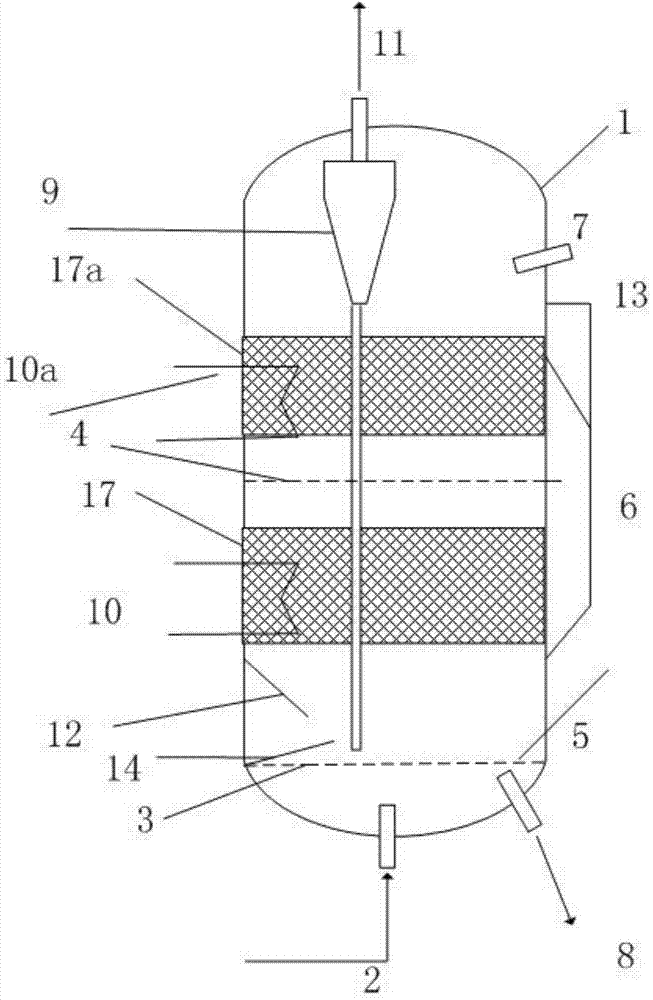
[0046] use as figure 1 In the double-stage fluidized bed regenerator 1 shown, the installation distance between the gas distributor 3 (porous plate type) and the horizontal gas distribution plate 4 above it is 10 times the diameter of the fluidized bed, and the overflow pipe is installed outside the regenerator 1 The surface of the outer wall, the overflow pipe 6a connecting the first-stage catalyst dense-phase area 5 and the second-stage catalyst dense-phase area 5a, the distance between the upper end and the first horizontal gas distribution plate 4 is the fluidized bed regenerator 1 diameter, the distance between its lower end installation position and the gas distributor 3 of the regenerator 1 is 0.7 times the diameter of the fluidized bed regenerator 1. The internal gas-solid separation device 9 is composed of a cyclone separator, the heat exchange method is an internal heat exchanger 10, and the heat exchange medium is water. The installation position of the lower end o...

Embodiment 2

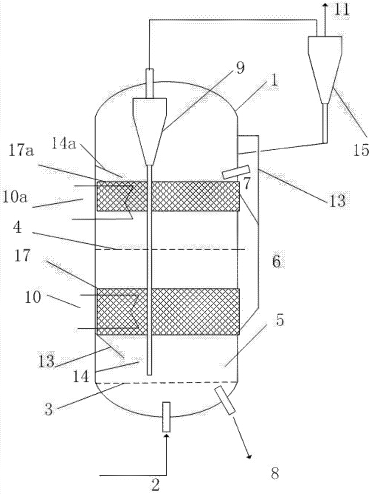
[0049] use as figure 2 In the shown two-stage fluidized bed regenerator 1 with external gas-solid separation device, the installation distance between the gas distributor 3 (cone type) and the horizontal gas distribution plate 4 above it is 0.5 times the diameter of the fluidized bed, and the overflow The flow pipe adopts the overflow pipe 6a placed on the surface of the outer wall of the regenerator to connect the first-stage catalyst dense-phase area 5 and the second-stage catalyst dense-phase area 5a, and its upper end is installed at a distance from the first transverse gas distribution plate 4 The distance is 0.2 times the diameter of the fluidized bed regenerator 1, and the distance between the lower end installation position and the gas distributor 3 of the regenerator 1 is 0.05 times the diameter of the fluidized bed regenerator 1. The installation position of the lower end of the overflow pipe degassing pipe 13 is connected with the upper end of the overflow pipe 6 a...

Embodiment 3

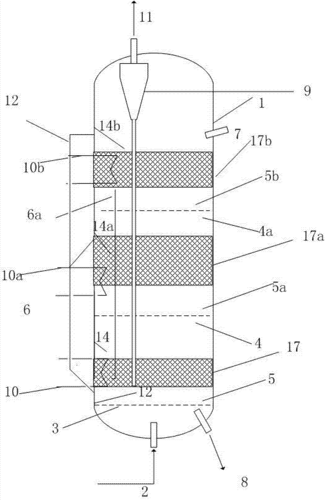
[0052] use as image 3 The shown three-stage fluidized bed regenerator 1 has a specific structure such that the installation distance between the gas distributor 3 (perforated plate) and the first horizontal gas distribution plate 4 above it is 4 times the diameter of the regenerator 1, and the second horizontal gas The installation distance between the distribution plate 4a and the first horizontal gas distribution plate 4 is 3 times the diameter of the regenerator 1, and the overflow pipe adopts the combination of external and internal, connecting the first catalyst dense phase zone 5 and the second catalyst dense phase The overflow pipe 6a in the area 5a adopts an external type, and the distance between the installation position of its upper end and the second horizontal gas distribution plate 4a is 0.5 times the diameter of the regenerator 1, and the distance between the installation position of its lower end and the gas distributor 3 is 1 0.5 times the diameter. The over...


PUM


Abstract

The invention belongs to the technical field of chemical technology process and equipment, and particularly relates to a catalyst regenerator and a catalyst regeneration method of methyl alcohol aromatization process. A multisection regeneration fluidized bed is internally and axially provided with one to a plurality of horizontal porous baffles so as to form two or a plurality of dense-phase zones for stacking catalysts; the one or a plurality of density-phase zones of the catalysts are internally provided with heat exchangers to control the temperature variation operation of gradually lowering the operation temperature in the density-phase zones which are arranged axially (from low to high); meanwhile, heat of the regenerator can be utilized comprehensively for preheating raw materials and generating steam. According to the invention, the problems of catalyst deactivation, shortening of integral service life and the like, which are caused by high-temperature scorching process, can be reduced obviously; meanwhile, the multisection regeneration fluidized bed is externally provided with a catalyst recovery system, so that catalyst particles can be recycled effectively in starting and under the working condition of instability, and the loss of the catalysts is reduced; the catalyst regenerator and the catalyst regeneration method have the characteristics of easiness in operation control and high safety.

Description

technical field [0001] The invention belongs to the technical field of chemical process and equipment, and in particular relates to a catalyst regenerator and a regeneration method for methanol aromatization process. Background technique [0002] Methanol aromatization technology is an emerging production process of aromatics. It is a process in which methanol is used as a raw material to generate aromatics such as benzene, toluene, xylene, and trimethylbenzene on a metal-molecular sieve dual-functional catalyst. The reaction temperature is 400-500°C, so the carbon deposition and deactivation of the catalyst is serious. At the same time, because the catalyst requires high acidity, high metal dispersion and activity, its deactivation phenomenon under high temperature and water vapor conditions is very serious. That is, while the deactivated catalyst needs to be regenerated by burning carbon, appropriate structure control is required to prevent the catalyst from losing its ac...

Claims


Application Information

Patent Timeline
Patent Type & Authority Patents(China)
IPC IPC(8): B01J38/34B01J38/32B01J38/04
Inventor 王彤魏飞汤效平骞伟中黄晓凡高长平崔宇丁焕德
Owner HUADIAN COAL IND GRP
Learn More