Polycrystalline silicon chip cutting method capable of saving steel wire

A cutting method and technology for polycrystalline silicon wafers, which are applied to fine working devices, stone processing equipment, manufacturing tools, etc., can solve the problem of high cost of cutting steel wires, save the amount of mortar, ensure processing efficiency, and facilitate chip removal.

Inactive Publication Date: 2014-04-02
JIANGSU ZHAOJING PHOTOELECTRIC TECH DEV
View PDF0 Cites 7 Cited by
  • Summary
  • Abstract
  • Description
  • Claims
  • Application Information

AI Technical Summary

Problems solved by technology

In the existing cutting technology, the cutting steel wire adopts a one-way cutting method, that is, the steel wire enters the wire from the head of the guide pulley through the pulley block from the pay-off pulley, exits from the tail of the guide pulley, enters the pulley block, and is wound on the take-up wire. On the reel, the cutting steel wire enters in a single direction, and the cutting steel wire on the take-up wheel will not be reused after cutting, so the cost of cutting steel wire is relatively high

Method used


Image

  • Polycrystalline silicon chip cutting method capable of saving steel wire

Examples


Embodiment 1

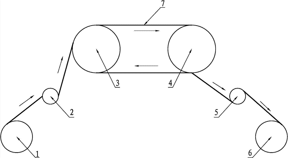
[0014] A polysilicon wafer cutting method that saves steel wires, such as figure 1 As shown, according to the prior art, the cutting steel wire 7 is released from the pay-off pulley 1, passes through the front pulley 2, enters the wire from the incoming wire guide pulley 3, and exits the wire from the outgoing wire guide pulley 4, and then passes through the rear pulley 5 and is wound on the take-up pulley 6. Above, the electrical control system controls the steel wire transmission mechanism including the pay-off wheel 1, the wire-in guide wheel 3, the wire-out guide wheel 4 and the wire-take-up wheel 6 to drive the cutting steel wire 7 between the wire-in guide wheel 3 and the wire-out guide wheel 4. The high-speed forward and reverse intervals alternately move in a straight line. The high-speed moving cutting steel wire 7 carries the silicon carbide in the mortar to cut the polysilicon ingot. The direction of rotation of the outgoing guide wheel 4 and the take-up wheel 6; af...


PUM

PropertyMeasurementUnit
sizeaaaaaaaaaa

Abstract

The invention discloses a polycrystalline silicon chip cutting method capable of saving a steel wire. A cutting steel wire is coiled in from a wire inlet guide wheel and coiled out from a wire outlet guide wheel through a front pulley after being released from a wire releasing wheel and is coiled on a wire retracting wheel through a rear pulley, an electric appliance control system comprises the wire releasing wheel, the wire inlet guide wheel, the wire outlet guide wheel and the wire retracting wheel, a steel wire transmission mechanism drives the cutting steel wire to do high-speed forward and reverse interval alternating linear motion so as to cut a polycrystalline silicon ingot, and the rotating directions of the wire releasing wheel, the wire inlet guide wheel, the wire outlet guide wheel and the wire retracting wheel can be alternately controlled by the electric appliance control system during a cutting process. The steel wire transmission mechanism is driven to rotate in 0.55-0.65 unit time according to an anticlockwise direction by the electric appliance control system after the steel wire transmission mechanism rotates in a unit time according to a clockwise direction, the rotation can be recurrently carried out in such a way, not only can the using amount of the cutting steel wire be reduced, but also the cutting action of silicon carbide cutting particles in mortar can be fully utilized, thus the using amount of the mortar is saved, and the processing cost of a polycrystalline silicon chip is reduced.

Description

technical field [0001] The invention relates to a processing technology of a polycrystalline silicon wafer, in particular to a cutting process of a solar polycrystalline silicon wafer. Background technique [0002] Solar polysilicon wafers are the most important raw materials for solar cells. A common production method for polysilicon wafers is multi-wire cutting. Multi-wire cutting is accomplished by a slicer. The slicer is equipped with a pulley block, a pay-off wheel, a wire guide wheel and a wire take-up wheel. The winding wheel drives the cutting steel wire to move in a straight line at a constant speed. When the cutting steel wire moves rapidly, it carries the mortar flowing down from the mortar curtain to grind and cut the ingot, thereby cutting the ingot into silicon wafers. In the existing cutting technology, the cutting steel wire adopts a one-way cutting method, that is, the steel wire enters the wire from the head of the guide pulley through the pulley block fr...

Claims


Application Information

Patent Timeline
Patent Type & Authority Applications(China)
IPC IPC(8): B28D5/04
Inventor 王德明杨方谈军王庆峰陈远峰
Owner JIANGSU ZHAOJING PHOTOELECTRIC TECH DEV
Why Eureka
Try Eureka