
Energy storage device and assembling method thereof

An energy storage device and negative electrode technology, which is applied in the direction of hybrid box/housing/package, hybrid capacitor collector, hybrid capacitor terminal, etc., can solve the problem that the sealing effect is greatly affected by the assembly process, the lead wire of the electrode unit is easily damaged, and the single O-type low cost of processing and molding, improved reliability, and easy assembly

Active Publication Date: 2014-04-02
KBR POWER QUALITY MANAGEMENT SHANGHAI
View PDF4 Cites 6 Cited by
  • Summary
  • Abstract
  • Description
  • Claims
  • Application Information

AI Technical Summary

Problems solved by technology

[0006] In the prior art, the sealing of the energy storage device is generally realized by a single O-ring or sealing gasket, and the sealing effect is greatly affected by the accuracy of the material and the assembly process
In addition, vibration and shock from the outside, the electrode unit inside the housing or the lead wires connected to the electrode unit are vulnerable to damage, which will lead to reduced reliability or shortened life of the energy storage device
[0007] In the prior art, the connection between the negative inner terminal and the negative outer terminal of the supercapacitor, and between the positive inner terminal and the casing is generally realized by interference fit, although the method can reduce the negative inner terminal and the negative electrode to a certain extent. However, during long-term use, external shocks (such as high and low temperature thermal shocks or external force shocks) and mechanical vibrations will increase or greatly fluctuate the internal resistance, making the storage Deterioration of performance of capable devices

Method used


Image

  • Energy storage device and assembling method thereof
  • Energy storage device and assembling method thereof
  • Energy storage device and assembling method thereof

Examples


Embodiment 1

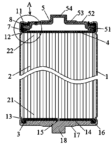
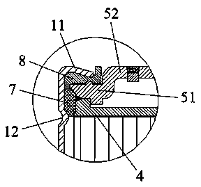
[0064] Please refer to figure 1 , figure 1 It is a schematic diagram of the cross-sectional structure of the energy storage device. The energy storage device includes a casing 1, a battery cell 2, a positive inner terminal 3, a negative inner terminal 4, a negative outer terminal 5 and an electrolyte. The casing 1 is cylindrical, and the electrolyte, the battery cell 2 , the positive inner terminal 3 and the negative inner terminal 4 are located inside the casing 1 . The bottom of the case 1 serves as the positive outer terminal, which is in contact with the positive inner terminal 3 . The housing 1 is made of metal or alloy, preferably aluminum or its alloy. An explosion-proof valve is also provided on the side wall of the housing 1, which is not shown in the figure.

[0065] The positive inner terminal 3 and the negative inner terminal 4 are respectively welded on the end faces of the positive electrode 21 and the negative electrode 22 of the cell 2 . The positive inner...

Embodiment 2

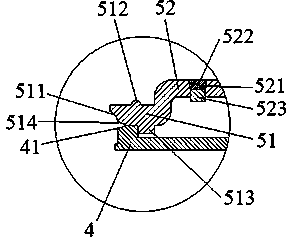
[0073] Please refer to Figure 5 , Figure 5 It is a partial structural diagram of another embodiment of the energy storage device of the present invention. In this embodiment, the energy storage device differs from the energy storage device in Embodiment 1 in that:

[0074] The cross-section of the downward positioning body 513 is triangular, which also has a good positioning effect; in this embodiment, the downward positioning body 513 is divided into four sections as a whole, and the four sections are symmetrically arranged in a ring shape;

[0075] The outer peripheral side 511 is an outwardly curved surface, which can increase the compression ratio of the O-ring 7;

[0076] The middle part of the S-shaped cross-section of the sealing gasket 8 is narrower. At this time, the inner wall of the curling edge 11 of the mouth of the housing 1 is a plane, and the sealing effect is better.

Embodiment 3

[0078] A method for assembling an energy storage device, comprising the steps of:

[0079] Step 1, welding and fixing the positive inner terminal 3 and the negative inner terminal 4 on the end surfaces of the positive pole 21 and the negative pole 22 of the battery cell 2 respectively;

[0080] Step 2, combining the negative external terminal 5 and the negative internal terminal 4 together by pressing in, the lower surface of the negative external terminal 5 and the upper surface of the negative internal terminal 4 are bonded together to form a joint;

[0081] Step 3, welding the joint, so that the negative outer terminal and the negative inner terminal form an assembly;

[0082] Step 4, set an O-shaped sealing ring 7 and a sealing gasket 8 on the outer periphery of the assembly;

[0083] Step 5, insert the positive inner terminal 3, the battery cell 2, the negative inner terminal 4, the negative outer terminal 5, the O-ring 7 and the gasket 8 into the housing 1 as a whole; ...


PUM


Abstract

The invention discloses an energy storage device. The energy storage device comprises a shell, a battery core, an anode inner terminal, a cathode inner terminal, a cathode outer terminal and electrolyte, wherein the anode inner terminal and the cathode inner terminal are respectively welded on the end surfaces of an anode and a cathode of the battery core, and the periphery of the anode inner terminal is inserted in an annular groove on the bottom wall of the shell; a welding seam is formed in a way that the cathode inner terminal and the cathode outer terminal are welded together, an O-shaped sealing ring can cover the welding seam, and a roll rim at the opening part of the shell is pressed on the cathode outer terminal through an annular sealing washer; an upper annular side bulge and a lower annular side bulge, which face the inner part of the shell and have pressing functions, are respectively arranged in the positions, which correspond to the cathode inner terminal and the anode inner terminal, on the side wall of the shell. The invention also discloses an assembling method of the energy storage device. The energy storage device disclosed by the invention has the advantages that the stability is good, the resistance is low, and the reliability is good; the structure is simple, the machining and forming cost is low, and the assembling is easy.

Description

technical field [0001] The invention relates to the technical field of energy storage devices, specifically, an energy storage device with simple structure, low internal resistance, long service life and high reliability, and also relates to an assembly method of the energy storage device. Background technique [0002] Currently, typical electrical energy storage devices are capacitors, supercapacitors, and batteries. Among them, a supercapacitor is a new type of energy storage device between a capacitor and a battery. Compared with traditional capacitors, supercapacitors have a higher specific capacity; compared with batteries, supercapacitors have higher specific power, can release large currents instantaneously, have short charging time, high charging efficiency, and long cycle life. Advantages such as memory effect and basic maintenance-free. Therefore, it has great potential application value in transportation, industry, renewable energy, power electronics, military, ...

Claims


Application Information

Patent Timeline
Patent Type & Authority Applications(China)
IPC IPC(8): H01G11/28H01G11/74H01G11/78H01G11/80H01G11/66H01G11/84
Inventor 张海林赵坤张奥林
Owner KBR POWER QUALITY MANAGEMENT SHANGHAI
Learn More