Hub motor on-load EMC performance test system

A hub motor and testing system technology, which is applied in the direction of motor generator testing, measuring electricity, measuring devices, etc., can solve the problems of high testing cost, unacceptable, difficult to purchase, etc., and achieve the effect of saving testing cost and reducing investment

Active Publication Date: 2014-04-16
CHINA AUTOMOTIVE ENG RES INST
View PDF6 Cites 16 Cited by
  • Summary
  • Abstract
  • Description
  • Claims
  • Application Information

AI Technical Summary

Problems solved by technology

[0008] 2. This scheme needs to open holes in the anechoic chamber, which seriously affects the performance of the anechoic chamber as a general test environment. Therefore, the adoption of this scheme requires the construction of a special radio anechoic chamber, which is extremely expensive
[0009] 3. This solution often needs to select different load motors for different motors under test, which will lead to higher investment in load motors by testing institutions
[0010] 4. When this scheme is adopted, the controllable and measurable parameters of the mo...

Method used


Image

  • Hub motor on-load EMC performance test system
  • Hub motor on-load EMC performance test system
  • Hub motor on-load EMC performance test system

Examples


Embodiment 1

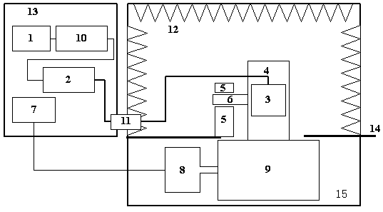
[0031] Example 1, such as image 3 As shown, the present invention tests the electromagnetic compatibility performance of the hub motor (including the hub motor and the wheel), and the test environment layout: power supply 1, hub motor controller 2, drum controller 7 and linear impedance stabilization network (LISN) 10 is arranged in a shielded control room 13 (such as a metal shielded room), and the hub motor 3, wheel 4, fixing device 5, and shaft 6 are arranged in an anechoic room 12 (such as a layer of electromagnetic wave-absorbing material is provided on the inner surface of the metal shielded room) On the ground 14 of the shielding room), the drum motor 8 and the drum 9 are arranged in the drum shielding room 15 (which has been well shielded during design and construction) under the ground 14 of the anechoic chamber 12 . The output of the power supply 1 is connected to the in-wheel motor controller 2 after passing through the linear impedance stabilization network 10, an...

Embodiment 2

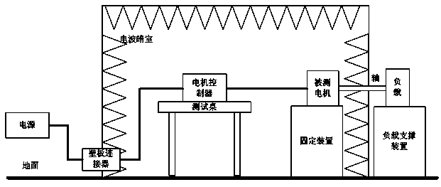
[0032] Example 2, such as Figure 4As shown, when the present invention tests the magnetic compatibility performance of the hub motor system including the hub motor, the hub motor controller and the power cable, the test environment layout: the power supply 1 and the drum controller 7 are arranged in the shielded control room 13, and the hub motor The controller 2, the hub motor 3, the wheel 4, the fixing device 5, the shaft 6 and the linear impedance stabilization network (LISN) 10 are arranged on the ground 14 of the anechoic chamber 12, and the drum motor 8 and the drum 9 are arranged in the anechoic chamber 12 In the drum shielded room 15 below the ground 14. The output of the power battery 1 enters the anechoic chamber 12 through the wall plate connector 11 of the anechoic chamber 12 through a well-shielded cable, and is connected to the hub motor controller 2 after passing through the linear impedance stabilization network 10, and the output of the hub motor controller 2...


PUM


Abstract

The invention relates to the technical field of electromagnetic compatibility tests, in particular to a hub motor on-load EMC performance test system. The system comprises a power source, a linear impedance stabilization network, a hub motor controller, a load exertion mechanism and a fixed device, wherein the power source controls a hub motor to rotate. A vehicle wheel where the hub motor is installed is connected with the fixed device through a shaft. The load exertion mechanism exerts loads on the contact surface of the vehicle wheel making contact with the load exertion mechanism, then hub motor on-load is achieved, meanwhile the fixed device is adjusted to control vertical loads of the vehicle wheel, and it is guaranteed that the vehicle wheel reliably makes contact with the load exertion mechanism. EMC performance of one signal hub motor and a hub motor system comprising the hub motor, the hub motor controller and a power cable can be tested, and the test result is not affected by the motor loads and is accurate and credible; in a general electromagnetic compatibility test environment which is already constructed and provided with a drum, a test environment which is expensive and special for motor electromagnetic compatibility does not need to be constructed, and therefore the cost for testing the hub motor is reduced.

Description

technical field [0001] The invention relates to the technical field of electromagnetic compatibility testing, in particular to an on-load EMC performance testing system for hub motors. Background technique [0002] Research on new energy vehicles is in full swing, among which electric vehicles are highly expected. The electric motor is the core drive component of an electric vehicle, and its role in an electric vehicle is equivalent to that of an engine in a conventional power vehicle. [0003] There are many schemes for the drive system of electric vehicles, and wheel drive is one of them. The wheel-side drive scheme means that each wheel is equipped with a motor to drive independently, and then the central controller coordinates all the tires of the vehicle according to the control strategy, so as to achieve the purpose of making all the tires of the vehicle work in harmony and make the vehicle run smoothly, safely and with high performance. [0004] Electric vehicles do...

Claims


Application Information

Patent Timeline
IPC IPC(8): G01R31/34G01R31/00
Inventor 雷剑梅黄雪梅陈立东赖志达李彪
Owner CHINA AUTOMOTIVE ENG RES INST
Why Eureka
Try Eureka