Gas guide type anaerobic reactor

A technology of anaerobic reactor and anaerobic reaction tank, applied in the field of anaerobic reactor, can solve the problems of high operating cost and investment cost, too many reaction levels, and high design requirements, and achieves convenient operation, good market prospect, Manufacture simple effects

Active Publication Date: 2014-04-23
SHANGHAI JIAO TONG UNIV
View PDF4 Cites 3 Cited by
  • Summary
  • Abstract
  • Description
  • Claims
  • Application Information

AI Technical Summary

Problems solved by technology

However, the disadvantages of this patent are: forced internal circulation requires large energy consumption, the system design requirements are relatively high, and the multi-stage anaerobic reactor is designed in the longitudinal direction, the reaction level should not be too many, the construction is complicated, and it is not convenient for engineering change
However, the disadvantages of this patent are: the circulation of sludge depends on the forced circulation of external power, which requires a lot of energy consumption, the reactor needs more baffles, more construction consumables, and the operating costs and investment costs are correspondingly high.
However, the disadvantage of this patent is that the sludge is deposited in the last stage of the reaction tank, the sludge retention of each stage is relatively low, and the amount of sludge produced is relatively large. If the sludge circulation is required, it needs to be forced by external power. cycle

Method used


Image

  • Gas guide type anaerobic reactor

Examples


Embodiment 1

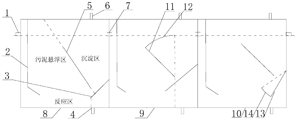
[0034] A multi-stage anaerobic reactor with gas diversion, its structure is as figure 1 As shown, it can be one anaerobic reaction tank, or multiple anaerobic reaction tanks connected in series. As shown in this embodiment, a primary anaerobic reaction tank 8 and a secondary anaerobic reaction tank 9 are provided until they are connected in series to n Grade anaerobic reaction tank 10. The reaction tanks are connected by welding. The upper part of each reaction tank is provided with an exhaust port 6, the bottom of the side is provided with a slag discharge port 4, and the first-level anaerobic reaction tank 8 is provided with a water inlet 1 from left to right. The water inlet 1 is at the upper end of the left side wall of the reaction tank. Waste water enters the reaction zone through the feed plate 2 and enters the sludge suspension area formed by the feed plate 2 and the deflector 5 under the action of the generated biogas. The angle between the plate 5 and the filling cov...

Embodiment 2

[0036] The difference between this embodiment and embodiment 1 is that the angle between the deflector 5 and the tank cover is 60°, the angle between the sludge plate and the right wall of the reaction tank is 30°, and the extension line from the deflector to the sludge plate The length of the sludge plate is about 1 / 10 of the length of the deflector, the distance from the bottom of the sludge plate to the bottom of the reaction tank is about 1 / 10 of the height of the reactor, and the length of the sludge plate protruding from the deflector is about the length of the sludge plate The ratio of the volume of the sludge suspension area to the volume of the sedimentation area is about 2:1. The embodiment of the present invention is applied to some aquaculture wastewater treatment in Hunan, and the water quality after being treated by a multi-stage anaerobic generator with gas diversion of the present invention: COD is 186mg / L, which is lower than the nationally allowed aquaculture p...

Embodiment 3

[0038] The difference between this embodiment and embodiment 1 is that the angle between the deflector 5 and the tank cover is 90°, the angle between the sludge plate and the right wall of the reaction tank is 30°, and the extension line from the deflector to the sludge plate The length of the sludge plate is about 1 / 10 of the length of the deflector, the distance from the bottom of the sludge plate to the bottom of the reaction tank is about 1 / 5 of the height of the reactor, and the length of the sludge plate protruding from the deflector is about the length of the sludge plate The ratio of the volume of the sludge suspension area to the volume of the sedimentation area is about 2:1. The embodiment of the present invention is applied to some aquaculture wastewater treatment in Hunan, and the water quality after treatment by a multi-stage anaerobic generator with gas diversion of the present invention: COD is 220 mg / L, which is lower than the nationally allowed aquaculture pollu...


PUM


Abstract

The invention relates to a gas guide type anaerobic reactor. The gas guide type anaerobic reactor comprises one or a plurality of anaerobic reaction tanks connected in series; a water inlet, a water outlet, an exhaust port and a slag outlet are formed in the outer part of each of the anaerobic reaction tanks; a feed plate, a guide plate and a sludge plate are arranged at the inner part of each of the anaerobic reaction tanks, wherein the feed plate is arranged at one side close to the water inlet; the sludge plate is arranged at one side close to the water outlet; the guide plate is arranged between the feed plate and the sludge plate; the guide plate and the sludge plate are movably connected to the inner part of each of the anaerobic reaction tanks; the feed plate and the guide plate define a sludge suspension area; the guide plate and the sludge plate define a precipitating area; a reaction area is formed in the bottom part of each of the reaction tanks. Compared with the prior art, the gas guide type anaerobic reactor has the advantages that the muddy water reaction time and the sludge precipitation time can be adjusted by controlling the volumes of the sludge suspension area and the sludge precipitating area; in addition, the gas guide type anaerobic reactor has good load to impact, and is high in fermenting efficiency, wide in applicable range, high in sludge utilization rate, low in energy consumption, simple in design, and convenient in equalization.

Description

Technical field [0001] The invention relates to the field of wastewater treatment, in particular to an anaerobic reactor with gas diversion. Background technique [0002] The anaerobic reactor is mainly used to treat livestock and poultry breeding wastewater, agricultural straw waste, and kitchen waste. The anaerobic reactor has gone through about three generations of reactors since its origin. The first generation of reactors has no separation of hydraulic retention time and sludge retention time, and the second generation of reactors achieves hydraulic retention time and sludge retention. In addition, anaerobic microorganisms can attach to the surface of the carrier to form granular sludge. The third-generation reactor further improves the good contact between the influent and the sludge. In short, each generation of the reactor is designed to form a large amount of sludge. Activated sludge and improve the direction of reactor mud-water contact are developed. Conventional ana...

Claims


Application Information

Patent Timeline
Patent Type & Authority Applications(China)
IPC IPC(8): C02F3/28
Inventor 唐庆丽申哲民王文昌
Owner SHANGHAI JIAO TONG UNIV
Why Eureka
Try Eureka