Differential power amplifier for CMOS with radio frequency of 0.1-1.2GHz

A differential power and amplifier technology, applied in the field of CMOS differential radio frequency power amplifier, can solve the problems of unsuitability for long-distance transmission, poor anti-interference ability, etc., and achieve the effect of good broadband impedance matching, good broadband characteristics and reducing chip area.

Inactive Publication Date: 2014-04-23
TIANJIN UNIV
View PDF4 Cites 11 Cited by
  • Summary
  • Abstract
  • Description
  • Claims
  • Application Information

AI Technical Summary

Problems solved by technology

Usually, the input signal and output signal of many RF power amplifiers are single-ended signals,

Method used


Image

  • Differential power amplifier for CMOS with radio frequency of 0.1-1.2GHz
  • Differential power amplifier for CMOS with radio frequency of 0.1-1.2GHz
  • Differential power amplifier for CMOS with radio frequency of 0.1-1.2GHz

Examples


Embodiment Construction

[0018] The circuit of the present invention will be further described in detail below in conjunction with the accompanying drawings and specific embodiments.

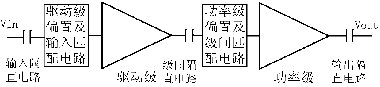
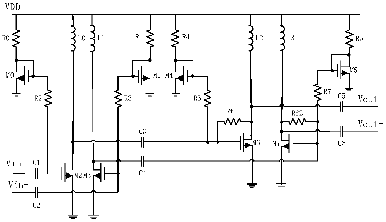
[0019] like figure 1 As shown, a 0.1-1.2GHz CMOS broadband radio frequency power amplifier with a differential structure of the present invention includes an input DC blocking circuit, a driver stage bias and an input matching circuit, a driver stage, a stage interval DC circuit, a power stage bias and a stage Between the matching circuit, the power stage and the output DC blocking circuit, the driver stage provides the drive gain and good input matching, that is, to ensure that the S11 parameters of the entire circuit meet the requirements; the power stage provides power gain and good output matching to ensure that the entire The power output of the circuit and good S22 parameters. The entire circuit has only one chip power supply, which is replaced by the voltage node VDD and powered by a 3.3V power supply. Both the...


PUM

PropertyMeasurementUnit
Inductance valueaaaaaaaaaa

Abstract

The invention discloses a differential power amplifier for a CMOS with the radio frequency of 0.1-1.2GHz. The differential power amplifier comprises an input blocking circuit, a drive stage polarization and input match circuit, a drive stage, an inter-stage blocking circuit, a power stage polarization and inter-stage match circuit, and a power stage and input blocking circuit. The drive stage provides drive gain and good input match. A power stage amplifying circuit provides power gain and good output match. The drive stage and the power stage amplifying circuit respectively comprise two NMOS tubes, two inductors, two current polarization circuits and two outer blocking capacitors. The power output stage comprises two feedback resistors and an inter-stage blocking capacitor. A common source structure is adopted, and the area of a chip is small. In the whole differential structure circuit, parameters of an adopted component can be determined after indexes of items such as the whole circuit gain, the bandwidth and the output power are integrated, and therefore the high gain, the high linearity and the high output power within 0.1-1.2GHz can be achieved.

Description

technical field [0001] The invention relates to the field of complementary metal oxide semiconductor (CMOS) frequency power amplifiers and integrated circuits, in particular to a CMOS differential radio frequency power amplifier for industry private network applications. Background technique [0002] The rapid development of wireless communication markets such as mobile phones, cordless phones, radio frequency tags (RFID), and wireless local area networks (WLAN) has continuously promoted the development of RF front-end transceivers in the direction of high integration, low power consumption, compact structure, and low price. The power amplifier (referred to as the power amplifier) ​​is an essential part of the wireless transmitter, and it is also the part that consumes the most energy in the entire transmitter, and the output power is generally relatively large. In order to improve the utilization rate of frequency spectrum, modern communication technology generally adopts t...

Claims


Application Information

Patent Timeline
IPC IPC(8): H03F3/45H03F3/20H03F3/189H03F1/42
Inventor 马建国王立果邬海峰周鹏王建利
Owner TIANJIN UNIV
Why Eureka
Try Eureka