

Precise positionable and compensable heavy-load mechanical arm
A technology of manipulators and mechanical fingers, which is applied in the field of precision heavy-duty manipulators, can solve the problems of restricting the development of degrees of freedom and the difficulty of ensuring the accuracy of operation, etc., and achieve the effects of realizing precision motion and safety assurance, ensuring precision, and improving high precision
- Summary
- Abstract
- Description
- Claims
- Application Information
AI Technical Summary
Problems solved by technology
Method used
Image

Examples
Embodiment Construction
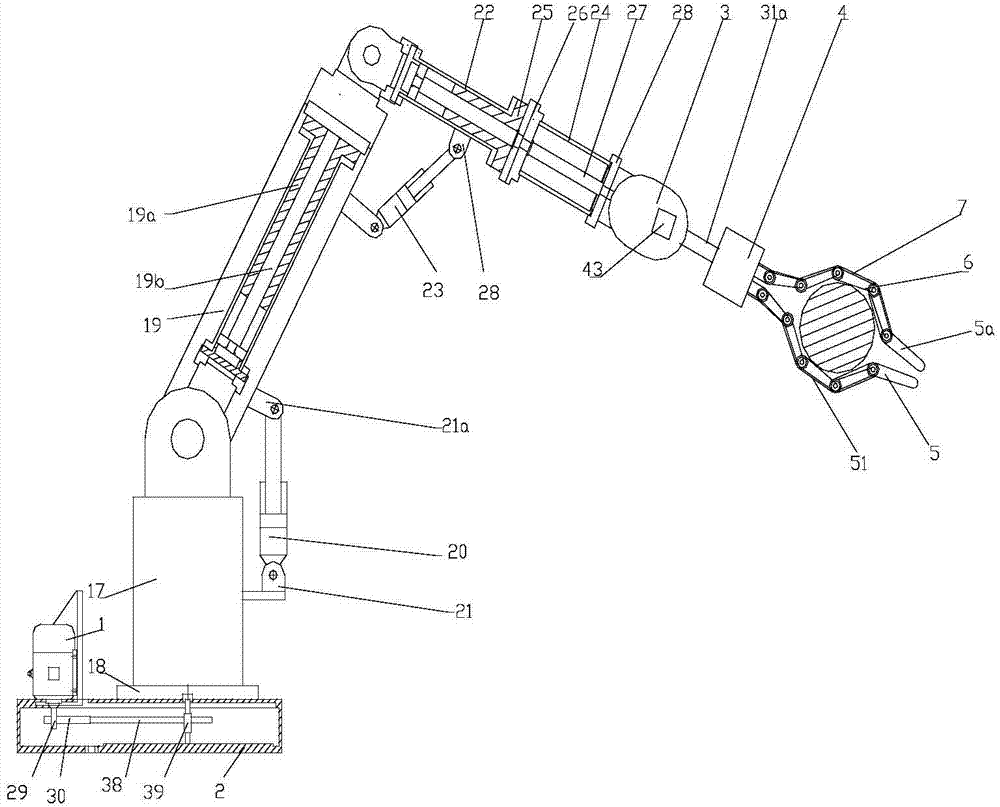
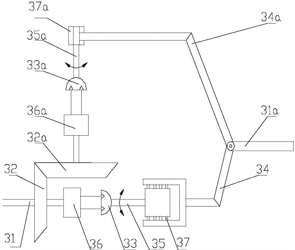
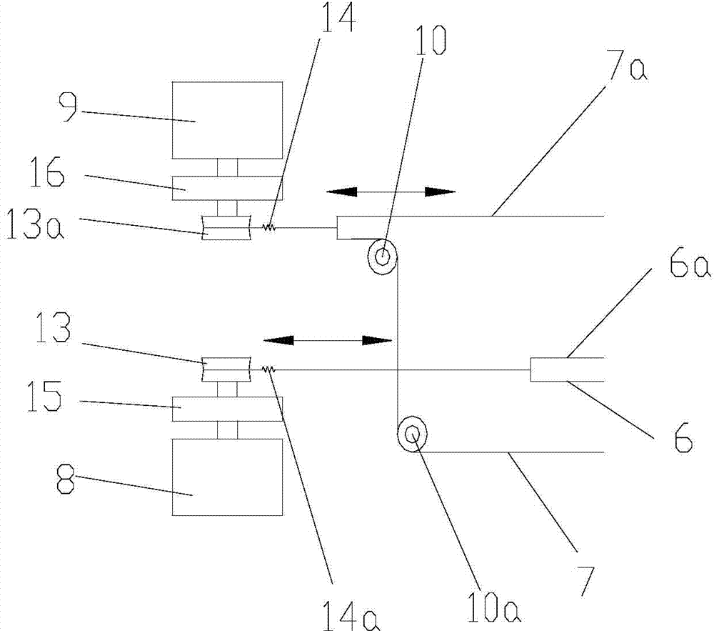
[0034] figure 1 It is a schematic diagram of the structure of the present invention, figure 2 A schematic diagram of the wrist assembly structure, image 3 It is a structural schematic diagram of the driving part of the flexible mechanical finger, Figure 4 It is a schematic diagram of the structure of the knuckle joint of the flexible mechanical finger, Figure 5 It is a schematic diagram of the automatic control system, as shown in the figure: the precision heavy-duty manipulator capable of positioning and compensation in this embodiment includes a power unit 1, a base 2, an arm assembly, a wrist assembly 3, a flexible hand and an automatic control system. The arm assembly includes a lower arm assembly, a middle arm assembly and an upper arm assembly;
[0035] Such as figure 2As shown, the wrist assembly includes a wrist input shaft 31, a driving bevel gear 32, a driven bevel gear 32a, a first swing hydraulic cylinder 33, a second swing hydraulic cylinder 33a and a wri...
PUM
 Abstract
Description
Claims
Application Information