A kind of stamping forming method of crankshaft speed signal disc

A technology of crankshaft speed and stamping forming, which is applied in transportation, packaging, vehicle parts, etc., can solve the problems of gas turbulence, unfavorable rapid production, long working hours, etc., and achieve the goal of simplifying the manufacturing method, reducing the cost of abrasive tools, and reducing the production cost Effect

Inactive Publication Date: 2015-09-02
GUANGXI UNIVERSITY OF TECHNOLOGY
View PDF5 Cites 2 Cited by
  • Summary
  • Abstract
  • Description
  • Claims
  • Application Information

AI Technical Summary

Problems solved by technology

[0006] The crankshaft speed signal plate produced by Scheme 1 needs to go through stamping, welding, drilling and other processes. The steps are cumbersome, and it is difficult to achieve high-precision fit of welded parts. The drilling process is complicated, and the turning process is difficult to locate. It is not conducive to mass and rapid production;
[0007] Although Plan 2 adopts one-time stamping and forming, the crankshaft speed signal plate produced is only made of steel plates that have not been punched out to form interval rectangular tooth tops, and the tooth tops are all cut out without outer ring structure. There is no connection between them, the structural strength of the teeth of the disc body is not high, it is easy to deform when running at high speed, and it is easy to form gas turbulence, causing noise

Method used


Image

  • A kind of stamping forming method of crankshaft speed signal disc
  • A kind of stamping forming method of crankshaft speed signal disc
  • A kind of stamping forming method of crankshaft speed signal disc

Examples


Embodiment Construction

[0044] A stamping forming method of a crankshaft speed signal disc, comprising the following steps:

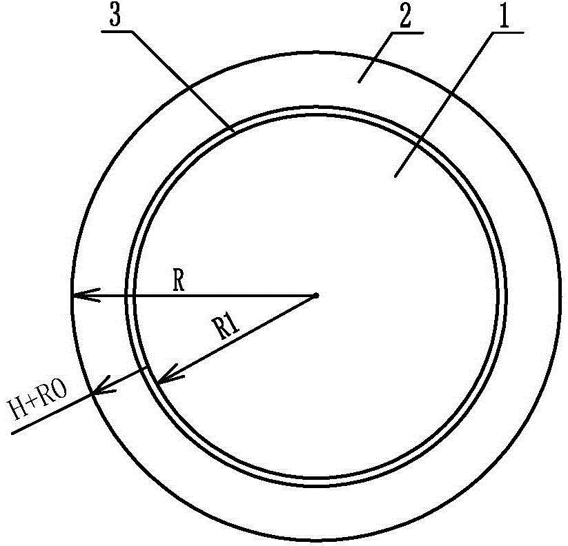
[0045] (1) Blanking: Punch the whole thin steel plate into a circular blank with dimensions including the height of the side ring and the width of the groove, that is, the radius of the circular blank is R=R1+R0+H, where R1 is the radius of the chassis 1 of the crankshaft speed signal disk, H is the height of the side ring 2 of the crankshaft speed signal disk, and R0 is the stamping allowance of the curved transition groove;

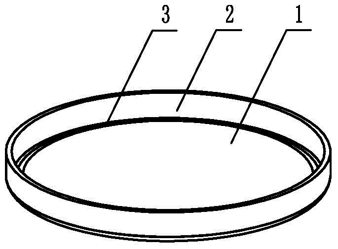
[0046] (2) Pressure groove: install the pressure groove composite mold on the vertical punching machine, and punch a curved transition groove 3 on the circumference of the chassis corresponding to the radius R1, that is, the joint between the chassis and the side ring of the signal plate;

[0047] (3) Deep drawing: use the drawing die to carry out bending and deep drawing, so that the side ring of the signal plate is flanged 90° along the curved transit...


PUM

PropertyMeasurementUnit
thicknessaaaaaaaaaa

Abstract

The invention provides a stamping forming method of an automobile crankshaft signal panel. The stamping forming method comprises a blanking process, a groove rolling process, a punching process, a deep drawing and flanging process, a large and small signal hole punching process, a reshaping process and the like. By applying the stamping forming method for a crankshaft rotating speed signal panel, a complicated porous-structure panel body and a cover body part can be manufactured by virtue of a stamping forming process, and the method has the advantages of fewer processes, simple operation and control, high material utilization, short production period, less environmental pollution and the like, is beneficial to realization of automatic large-batch production and can be used for improving the production efficiency and lowering the production cost; signal hole processing is performed after metallic material plastic deformation, hole processing is more accurate, and the method can be used for solving the problems such as irregular shape of deep-drawn rectangular teeth, deformation of deep-drawn holes of a complicated-structure piece and high cracking, wrinkling and deformation possibility of a panel body due to uneven stress strain in a rectangular tooth primary stamping forming method, and can be applied to large-batch production of automobile parts.

Description

technical field [0001] The invention relates to a processing method of vehicle parts, in particular to a stamping forming method of a crankshaft speed signal disc. Background technique [0002] The existing automobile engine crankshaft speed signal discs have roughly the same shape. For thin-walled disc-like parts with mounting holes and positioning holes on the plane and dense and uniform rectangular holes on the side, the traditional manufacturing methods commonly used are: [0003] 1. Combination welding after processing separately: first process the plate surface, prepare materials, blanking, stamping, deburring, punching, and then weld with the drilled ring, and remove the excess weld marks; [0004] 2. The thin steel plate is punched into a disc at one time. There are mounting holes and positioning holes on the disc, and there are rectangular teeth around the disc body. [0005] The disadvantages are: [0006] The crankshaft speed signal plate produced by Scheme 1 ...

Claims


Application Information

Patent Timeline
Patent Type & Authority Patents(China)
IPC IPC(8): B21D35/00B21D53/88
Inventor 李健袁杰黄红生窦凤楼乔萌张豫宁
Owner GUANGXI UNIVERSITY OF TECHNOLOGY
Why Eureka
Try Eureka