
Method for performing laser cladding by using multiple lasers

A laser cladding and multi-laser technology, which is applied in the field of laser processing, can solve the problems of cracks and pores in the cladding layer, low laser cladding efficiency, and high processing costs, and achieve no cracks and pores, reduce processing costs, and automate high degree of effect

Inactive Publication Date: 2014-05-07
INST OF SEMICONDUCTORS - CHINESE ACAD OF SCI
View PDF5 Cites 26 Cited by
  • Summary
  • Abstract
  • Description
  • Claims
  • Application Information

AI Technical Summary

Problems solved by technology

In the specific implementation process, there are two prominent problems that the laser cladding process often encounters in industrial applications: one is that the efficiency of laser cladding is low, resulting in high processing costs; the other is that the cladding layer is prone to cracks and pores, which limits application of the technology
In order to solve the above-mentioned engineering bottlenecks, some researchers have disclosed a dual-beam laser rapid cladding method (patent application number: CN201110352255.0). Two laser beams after one, this method limits the energy ratio of the two laser beams, and the versatility is poor

Method used


Image

  • Method for performing laser cladding by using multiple lasers
  • Method for performing laser cladding by using multiple lasers
  • Method for performing laser cladding by using multiple lasers

Examples


Embodiment 1

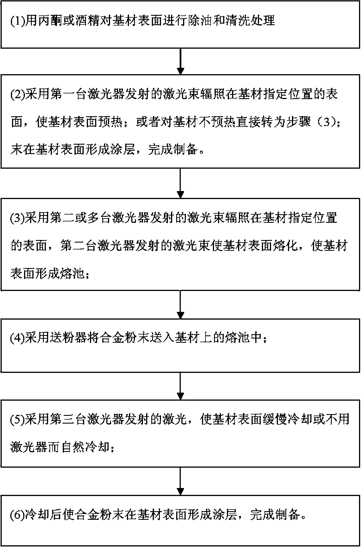
[0039] The implementation process of this embodiment is as follows figure 2 shown.

[0040] (1) Wipe off the oil stains on the surface of Q235 substrate A with acetone;

[0041] (2) The laser beam output by the first laser is focused on the surface of the Q235 substrate A through the laser head 1, and preheated to increase the absorption rate of the Q235 substrate A to the laser beam of the second laser, and reduce the laser cladding process. Thermal stress, the laser power of the first laser is 600W, so that the preheating temperature of the substrate is 400-500°C;

[0042] (3) The laser beam output by the second laser irradiates the surface of the Q235 substrate A through the laser head 2 to melt the surface of the Q235 substrate (A) to form a molten pool; the laser power of the second laser is 1.2kW;

[0043](4) The laser head 2 of the second laser is equipped with a synchronous powder feeding nozzle, and the powder feeder and the synchronous powder feeding nozzle are us...

Embodiment 2

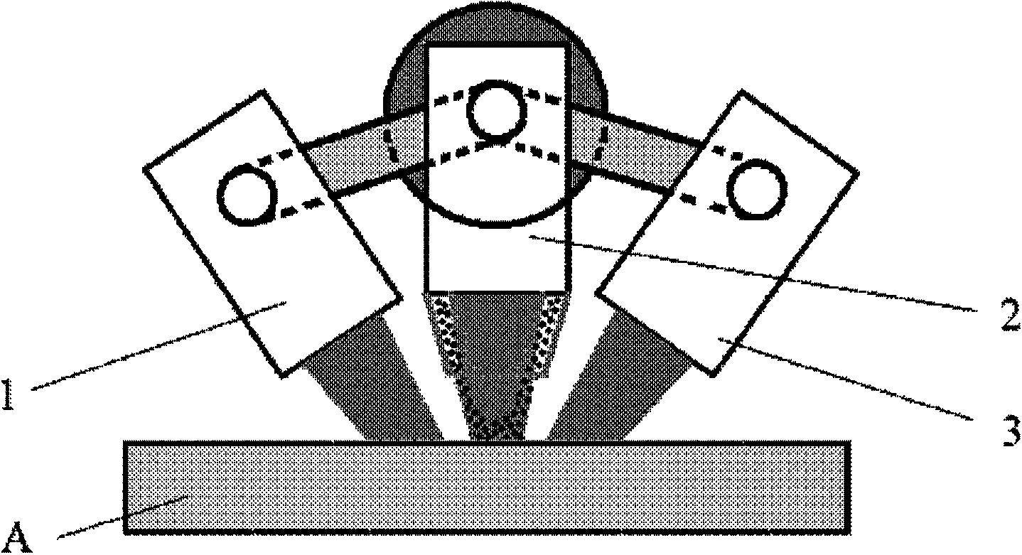
[0047] The implementation process of this embodiment is as follows image 3 shown.

[0048] (1) Wipe off the oil stains on the surface of 27SiMn hydraulic prop A with acetone;

[0049] (2) There is no preheating in the laser cladding process, and three 1KW fiber lasers are used for laser cladding directly;

[0050] (3) The laser beams generated by the three lasers are focused on the same position on the surface of the 27SiMn hydraulic prop A through the processing heads 1, 2, and 3, so that the surface of the 27SiMn hydraulic prop A is melted to form a molten pool. The spot diameters of the three laser beams of the three lasers Both are 3mm, and the center of the light spot on the surface of the substrate completely overlaps. The power of each laser is 800W, which is equivalent to a 2400W laser for laser cladding processing:

[0051] (4) The laser head 2 of the second laser is equipped with a synchronous powder feeding nozzle. Fe-based alloy powder is fed into the molten po...

Embodiment 3

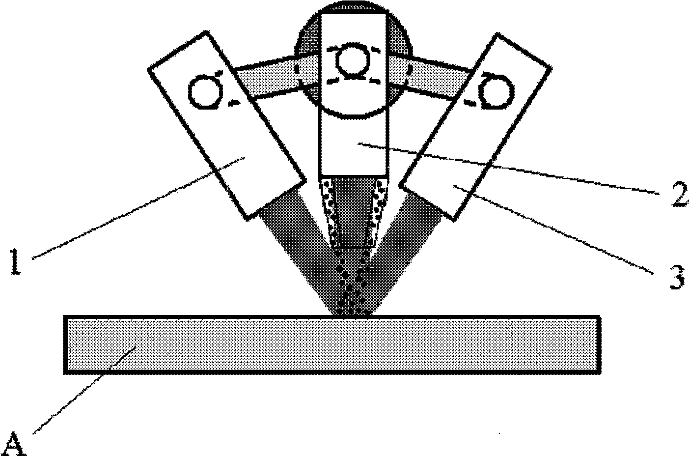
[0055] The implementation process of this embodiment is as follows Figure 4 shown.

[0056] (1) Wipe off the oil stains on the surface of 304 stainless steel A with acetone;

[0057] (2) There is no preheating in the laser cladding process, and three 2KW solid-state lasers are used for laser cladding directly;

[0058] (3) The laser beams generated by the three lasers are focused on the surface of 304 stainless steel A through processing heads 1, 2, and 3. The spot diameter of the three laser beams on the surface of 304 stainless steel A is 4mm, and the three spots overlap. The second laser The laser power output by the laser head 2 of the first laser is 1200W, and the laser power output by the laser head 1 of the first laser and the laser head 3 of the third laser are both 1600W.

[0059] (4) using a powder feeder and a separately configured lateral powder feeding nozzle 4 to feed the Ni-based alloy powder into the molten pool of the base material;

[0060] (5) Natural co...


PUM

PropertyMeasurementUnit
thicknessaaaaaaaaaa

Abstract

The invention discloses a method for performing laser cladding by using multiple lasers. The method comprises the following steps: performing oil-removing and cleaning treatment on the surface of a substrate by using acetone or alcohol; irradiating laser beams emitted by a first laser onto the surface of a specified position on the substrate to preheat the surface of the substrate; or directly turning to step 3 without preheating the substrate; irradiating laser beams emitted by a second or multiple lasers onto the surface of a specified position on the substrate to melt the surface of the substrate in order to form a molten pool on the surface of the substrate; feeding alloy powder into the molten pool on the substrate by using a powder feeder; and slowly cooling the surface of the substrate by using laser light emitted by a third laser or naturally cooling without using the laser to form a coating on the surface of the substrate in order to complete preparation. The method has the advantages of laser cladding efficiency, lower machining cost, good bonding of the substrate, convenience in operation and high automation degree.

Description

technical field [0001] The invention belongs to the technical field of laser processing, in particular to a method for laser cladding with multiple lasers. Background technique [0002] As an emerging surface modification technology, laser cladding technology is widely used in the strengthening and repairing process of mining machinery, iron and steel metallurgy and other parts due to its advantages of green, pollution-free and high efficiency. In the specific implementation process, there are two prominent problems that the laser cladding process often encounters in industrial applications: one is that the efficiency of laser cladding is low, resulting in high processing costs; the other is that the cladding layer is prone to cracks and pores, which limits application of this technology. In order to solve the above-mentioned engineering bottlenecks, some researchers have disclosed a dual-beam laser rapid cladding method (patent application number: CN201110352255.0). One a...

Claims


Application Information

Patent Timeline
Patent Type & Authority Applications(China)
IPC IPC(8): C23C24/10
Inventor 林学春赵树森刘发兰王奕博周春阳高文焱
Owner INST OF SEMICONDUCTORS - CHINESE ACAD OF SCI
Learn More