A co boiler with denitrification function

A boiler and functional technology, applied in the field of CO boilers with denitrification function, can solve the problems of uneven mixed denitrification equipment, high investment, low flue gas denitrification efficiency, etc., to improve heat utilization efficiency, simplify equipment structure, save The effect of equipment investment

Active Publication Date: 2016-06-22
CHINA PETROLEUM & CHEM CORP +1
View PDF7 Cites 0 Cited by
  • Summary
  • Abstract
  • Description
  • Claims
  • Application Information

AI Technical Summary

Problems solved by technology

[0010] Aiming at the problems of low flue gas denitrification efficiency, uneven mixing of flue gas and ammonia gas, large area occupied by denitrification equipment and high investment in the prior art, the present invention provides a CO boiler with denitrification function, which can effectively improve the efficiency of flue gas and ammonia Improve gas mixing uniformity, improve denitrification efficiency and prevent ammonia escape, and save equipment investment

Method used


Image

  • A co boiler with denitrification function
  • A co boiler with denitrification function
  • A co boiler with denitrification function

Examples


Embodiment 1

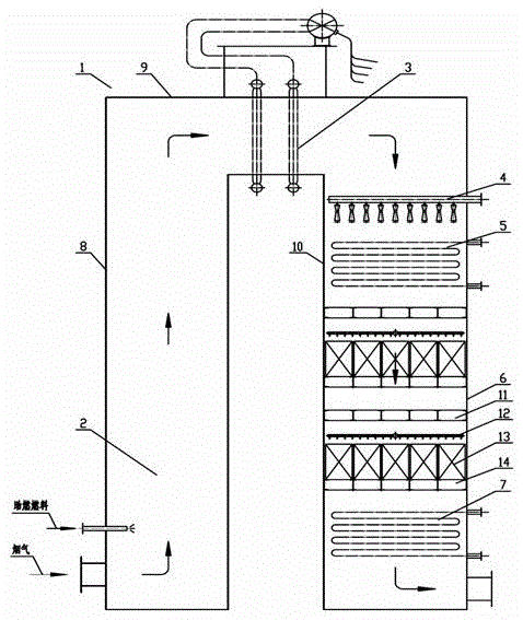
[0028] Depend on figure 1 As shown, the present invention provides a CO boiler with denitrification function. The boiler includes a flue 1, a combustion chamber 2, a steam drum 3, an evaporation section 5 and an economizer section 7, and the flue includes a first Vertical flue 8, horizontal flue 9 and the second vertical flue 10, the two ends of the horizontal flue 9 communicate with the top of the first vertical flue 8 and the second vertical flue 10 respectively, the combustion chamber 2 is set in the first vertical flue 8, the steam drum 3 is set in the horizontal flue 9, the evaporation section 5 and the economizer section 7 are set in the second vertical flue 10, wherein the boiler also It includes an ammonia injection mixing mechanism 4 and a denitration reactor 6, the ammonia injection mixing mechanism 4 is arranged in the second vertical flue 10 above the evaporation section 5, and the denitration reactor 6 is located in the evaporation section 5 and the economizer sec...

Embodiment 2

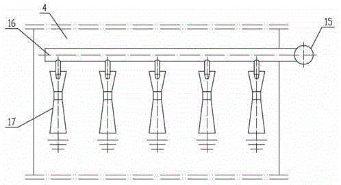
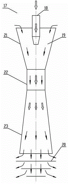
[0031] In the boiler of the present invention, the ammonia injection mixing mechanism 4 includes an ammonia injection main pipe 15, an ammonia injection branch pipe 16 and an ammonia injection element 17. 15, and the other end is a closed structure; the ammonia injection element 17 includes a nozzle 18, a diffuser 19 and a splash plate 20, and the lower surface of the ammonia injection branch pipe 16 is connected to the ammonia injection element 17 through the nozzle 18. The diffuser 19 includes a constriction section 21 , a throat 22 and an expansion section 23 from top to bottom. Among them, the contraction angle of the contraction section is 15°-30°, the expansion angle of the expansion section is 10°-20°, the length of the throat is 1-3 times the diameter of the throat, and the distance between the splash plate and the horizontal section of the outlet of the expansion section is the length of the throat 80% to 120% of 80% to 120% of the splash plate 4; the splash plate 4 h...


PUM


Abstract

The invention relates to a CO boiler having the denitration function. The CO boiler comprises a flue, a combustion chamber, steam drums, an evaporation section and an economizer section. The flue comprise a first vertical flue body, a horizontal flue body and a second vertical flue body, wherein the two ends of the horizontal flue body are communicated with the upper portion of the first vertical flue body and the upper portion of the second vertical flue body respectively, the combustion chamber is arranged in the first vertical flue body, the steam drums are arranged in the horizontal flue body, and the evaporation section and the economizer section are arranged in the second vertical flue body. The CO boiler further comprises an ammonia spraying and mixing mechanism and a denitration reactor. The ammonia spraying and mixing mechanism is arranged in the second vertical flue body and is located above the evaporation section. The denitration reactor is arranged between the evaporation section and the economizer section. The CO boiler having the denitration function can effectively improve the mixing uniformity of smoke and ammonia gas, improve the denitration efficiency and prevent ammonia escape; due to the fact that the denitration reactor is arranged in the CO boiler, an ammonia mixing grid is not needed, the utilization efficiency of smoke heat is improved, and the occupied space of the CO boiler and equipment investment are reduced.

Description

technical field [0001] The invention relates to a flue gas treatment device, in particular to a CO boiler with denitrification function. Background technique [0002] Nitrogen oxides (NO x ) is one of the main pollution sources of air pollution. In the occupational environment, it is exposed to several gas mixtures, often called gunpowder (gas), mainly NO and NO 2 , to NO 2 Mainly. NO x All have varying degrees of toxicity, with NO and NO 2 Mainly NO x It is an important cause of photochemical smog and acid rain. NO in automobile exhaust x Toxic smog formed by the reaction of hydrocarbons with ultraviolet radiation is called photochemical smog. Photochemical smog has a characteristic odor, irritates the eyes, damages plants, and can reduce atmospheric visibility. In addition, NO x Nitric and nitrous acids that react with water in the air are components of acid rain. NO x The harm to the human body is mainly manifested in the damage to the respiratory tract. [0...

Claims


Application Information

Patent Timeline
Patent Type & Authority Patents(China)
IPC IPC(8): F23J15/04B01D53/86B01D53/79B01D53/56
Inventor 彭德强李欣齐慧敏刘志禹陈新王明星王岩
Owner CHINA PETROLEUM & CHEM CORP
Why Eureka
Try Eureka