
Internal combustion heating rotary vane biomass pyrolysis liquefaction device

A biomass pyrolysis and liquefaction device technology, applied in the field of pyrolysis and liquefaction devices, can solve the problems of complex material pretreatment, strict requirements on feed particle size, and strict requirements on types, so as to improve the efficiency of biomass liquefaction and pyrolysis Effect of liquefaction strength and reduction of production cost

Inactive Publication Date: 2015-09-09
HEFEI UNIV OF TECH
View PDF6 Cites 0 Cited by
  • Summary
  • Abstract
  • Description
  • Claims
  • Application Information

AI Technical Summary

Problems solved by technology

The problem with this method is: the combustion of the two by-products will produce water vapor, and the water vapor will eventually be condensed into the bio-oil along with the pyrolysis gas, thereby having a great impact on the properties of the bio-oil; There will be residual oxygen, and the presence of oxygen will change the pyrolysis pathway of biomass and greatly reduce the yield of bio-oil; and the gases generated by combustion will also undergo heating and cooling processes. In addition, these gases also dilute the pyrolysis process. The non-condensable gas produced greatly reduces its calorific value, which brings difficulties to its application
The technical difficulty lies in the control of sand circulation and temperature
In addition, since the circulation of sand is generally very large, the energy consumption of the circulation process and the wear caused by high-temperature sand must be considered.
The fourth is to use the high-temperature flue gas from the combustion of by-products to flow through the side wall interlayer of the special reactor to provide the required heat for the pyrolysis reaction. Limited heat transfer, low thermal efficiency
[0004] At present, the reactors used to realize the pyrolysis and liquefaction of biomass are mainly fluidized bed reactors, which have the advantages of high heat transfer rate and short particle residence time, which is conducive to improving the efficiency of biomass pyrolysis to produce liquid fuels. : First, strict requirements on the types of materials and poor adaptability; second, strict requirements on the particle size of feed materials, which makes the pretreatment of materials before biomass pyrolysis complicated and increases the cost
[0005] The above-mentioned defects in the process of biomass pyrolysis and liquefaction have greatly affected the cost of bio-oil produced by biomass pyrolysis and liquefaction, and restricted the industrial application of existing biomass pyrolysis and liquefaction technology

Method used


Image

  • Internal combustion heating rotary vane biomass pyrolysis liquefaction device
  • Internal combustion heating rotary vane biomass pyrolysis liquefaction device

Examples


Embodiment Construction

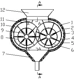
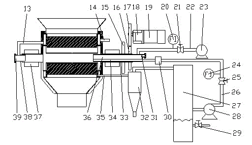
[0024] see figure 1 and figure 2 , using a quasi-elliptical cylindrical reactor 1, the reactor 1 is arranged axially and horizontally, the side wall of the reactor 1 is set as a jacket structure, and the jacket is sequentially composed of pyrolysis layer 6, pyrolysis layer wall 5, Hot waste gas layer 4, hot waste gas layer wall 3 and insulation layer 2; track 11 is set on pyrolysis layer wall 5; two horizontal internal combustion rotary pipes 8 are set at the same height below the center plane of reactor 1, and two internal combustion rotary pipes 8, a plurality of slit plates 9 are arranged alternately along the circumference of its wall. The slits of the slit plates 9 are not connected to the inside of the internal combustion rotating pipe 8. Blades 10 are arranged in the gaps of the slit plates 9, and the extended ends of the blades 10 are connected to the track 11 connections; the two ends of each internal combustion rotating pipe 8 are concentrically connected to two ro...


PUM


Abstract

The invention discloses an internal-combustion heating rotary vane type biomass pyrolysis liquefying device. The sidewall of a reactor is configured as a jacket structure; the jacket comprises a pyrolysis layer, a pyrolysis layer wall, a hot waste gas layer, a hot waste gas layer wall and a heat insulating layer in sequence from inside to outside, wherein a track is arranged on the pyrolysis layer wall; two horizontal internal-combustion rotating pipelines are arranged at the same height below a central plane of the reactor; a plurality of vane gap plates are alternately arranged inside the two internal-combustion rotating pipelines along the circumferences of the walls of the internal-combustion rotating pipelines; gaps of the vane gap plates are not communicated with the inside of each internal-combustion rotating pipeline; vanes are arranged inside the gaps of the vane gap plates; the protruding ends of the vanes are connected with the track; a feed hopper is arranged above the reactor and communicated with the pyrolysis layer; a conical furnace bottom is supported at the bottom of the reactor and communicated with the pyrolysis layer; a slag discharging opening is formed in a conical bottom opening. The internal-combustion heating rotary vane type biomass pyrolysis liquefying device disclosed by the invention is used for greatly increasing the biomass liquefaction rate and the bio-oil heat value, improving the properties and reducing the biomass liquefaction cost, and is suitable for production of bio-oil by use of various biomass raw materials, and simple and convenient to operate, manage and maintain.

Description

technical field [0001] The invention relates to a pyrolysis liquefaction device, more specifically a pyrolysis liquefaction device using biomass as raw material. Background technique [0002] Biomass mainly includes forestry materials, agricultural waste, municipal waste and livestock and poultry manure. Biomass is a kind of renewable energy with abundant reserves, which can be used as an alternative energy source to achieve CO 2 Zero emission and low S and N content can greatly reduce the greenhouse effect and environmental pollution. Biomass pyrolysis liquefaction refers to the direct pyrolysis of biomass under the conditions of medium temperature, high heating rate and extremely short gas residence time under the condition of complete anoxic or limited oxygen supply, and the product is rapidly cooled to obtain High yields of liquid fuels known as bio-oils. Factors affecting the effect of biomass pyrolysis liquefaction include heating rate, reaction temperature, residen...

Claims


Application Information

Patent Timeline
Patent Type & Authority Patents(China)
IPC IPC(8): C10G1/00C10B53/02C10B47/18
CPCY02E50/14Y02E50/10
Inventor 胡孔元陈天虎
Owner HEFEI UNIV OF TECH
Learn More