Combination fluid dynamic pressure groove mechanical seal ring capable of automatically discharging particles

A technology of mechanical seal and combined fluid, which is applied in the direction of engine seal, mechanical equipment, engine components, etc., can solve the problems of mechanical seal loss of dynamic pressure effect, mechanical seal particle wear failure, seal failure and other problems, and achieve enhanced fluid film bearing capacity , Improve the friction and lubrication state, reduce the effect of end face wear

Inactive Publication Date: 2014-05-14
JIANGSU UNIV
View PDF13 Cites 20 Cited by
  • Summary
  • Abstract
  • Description
  • Claims
  • Application Information

AI Technical Summary

Problems solved by technology

These sealing technologies can achieve good results when transporting some impurities-free media, but in the case of transporting petroleum and chemical industries containing particles and impurities, solid particles are often sucked between the sealing end faces due to this type of mechanical seal. If it cannot be removed in time, the micro-molding of the sealing end face will become blocked and fail to play the role of dynamic pressure sealing application. At the same time, abrasive wear will occur, resulting in seal failure and serious accidents.
[0003] In recent years, the main solution to problems such as mechanical seal particle wear and failure is: by adding auxiliary systems, adopting measures such as filtration, flushing, separation, and isolation, but this often leads to higher costs and more complicated structures; The outer cover is covered with an isolation sleeve to avoid direct contact between the elastic element and the medium, but the stress on the sealing end face is changed, and the cost is also high
Aiming at the problem of mechanical seal end face inhalation of solid particles and wear, some researcher

Method used


Image

  • Combination fluid dynamic pressure groove mechanical seal ring capable of automatically discharging particles
  • Combination fluid dynamic pressure groove mechanical seal ring capable of automatically discharging particles
  • Combination fluid dynamic pressure groove mechanical seal ring capable of automatically discharging particles

Examples


Embodiment Construction

[0013] The combined dynamic pressure groove in the present invention is opened on the dynamic ring of the mechanical seal, and the end surface modification can be processed by electric spark, electrochemical corrosion, laser processing and other processes.

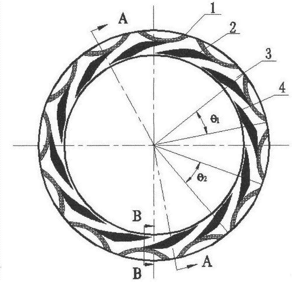
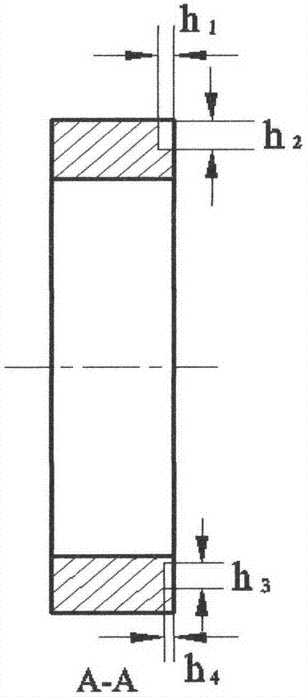
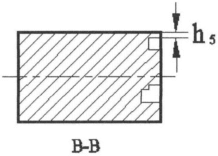
[0014] Arc grooves (1) and pumping grooves (2) symmetrically distributed along the rotation center are provided on the mechanical seal moving ring, such as figure 1 As shown, the pumping groove type is a helix, the helix angle θ=18°, and the groove depth h 4 =3μm, groove length h 3 =6mm, groove and weir width ratio γ=1, number of grooves N g =12, θ 2 =30°, arc groove type is circular, groove width=2mm, groove depth h 1 =8μm, outer arc width h 2 =3.25mm, θ 1 =27°, seal dam (4) width h 5 =0.5mm, the area around the groove on the sealing end face is the sealing weir (3), and the arc length between the outer arc of the arc groove (1) and the end of the spiral groove (2) is 0.4 of the width of the spiral groove.

[0015]...


PUM


Abstract

The invention relates to a combination fluid dynamic pressure groove mechanical seal ring structure capable of automatically discharging particles. The combination fluid dynamic pressure groove mechanical seal ring structure is characterized in that on a sealing moving ring or a static ring, a circulation outer circle arc groove and a pumping groove which are symmetrically arranged about the rotation center are sequentially arranged from the high-pressure side and the low-pressure side. The outer circle arc groove is formed in the upper portion (high-pressure side) of the end face and the pumping groove is formed in the lower portion (low-pressure side) of the end face. The arc groove and the pumping groove are communicated at the contact place so as to ensure that the particles entering the pumping groove enter the arc groove by means of the pumping effect and return to a sealing cavity through medium circulation. Meanwhile, by means of the dynamic pressure effect and the pumping effect of the arc groove and the pumping groove, the bearing capacity and the low leakage amount of a liquid film are ensured. Thus, the good sealing capacity and the automatic particle discharging capacity of the combination fluid dynamic pressure groove mechanical seal can be achieved. The dynamic pressure groove is prevented from being blocked and abrasion of the sealing end face is relieved. The seal ring can be applied to working conditions including solid particle media.

Description

technical field [0001] The present invention relates to fluid mechanical seal technology and fluid dynamic pressure lubrication theory, specifically refers to a mechanical seal liquid film bearing capacity and low leakage as the premise, automatic excretion of micro particles entering the sealing end face, preventing the pumping groove from clogging and losing the pump. increases delivery capacity, minimizes leakage, reduces face wear and extends mechanical seal life. Background technique [0002] In modern industrial applications, in order to meet the strict requirements of zero leakage, low wear and long service life of mechanical seals in aerospace, nuclear power, petrochemical and other industries, surface modification sealing technologies (dry gas sealing technology, upstream pumping mechanical Sealing technology, thermal fluid dynamic sealing technology, etc.), multi-face sealing technology, monitoring sealing technology, combined sealing technology, etc. Its ultimate...

Claims


Application Information

Patent Timeline
IPC IPC(8): F16J15/34F16J15/40
Inventor 陈汇龙吴强波邹强刘金凤付杰
Owner JIANGSU UNIV
Why Eureka
Try Eureka