
Rapid spectrum scanning liquid crystal electric control adjustable optical filter

A spectral scanning and optical filter technology, applied in the field of spectral imaging, can solve problems such as inaccurate spectral data extraction, slow spectral scanning speed, and blurred spectral images, so as to improve spectral scanning speed and spectral imaging frame rate, and improve spectral scanning Speed, the effect of increasing the frame rate of spectral imaging

Inactive Publication Date: 2014-05-14
INST OF FLUID PHYSICS CHINA ACAD OF ENG PHYSICS
View PDF4 Cites 5 Cited by
  • Summary
  • Abstract
  • Description
  • Claims
  • Application Information

AI Technical Summary

Problems solved by technology

[0003] At present, the response time of spectral imaging equipment provided by CRI in the United States is generally 50ms-150ms, and the imaging frame rate is 7-20 frames per second. During spectral scanning imaging, the slow spectral scanning speed will lead to blurred spectral images and inaccurate spectral data extraction, which will affect the results of spectral identification and seriously affect the application of spectral imaging equipment based on liquid crystal electronically controlled adjustable filters in remote sensing detection, medical diagnosis, Applications in environmental protection monitoring, agricultural and forestry censuses and other fields

Method used


Image

  • Rapid spectrum scanning liquid crystal electric control adjustable optical filter
  • Rapid spectrum scanning liquid crystal electric control adjustable optical filter
  • Rapid spectrum scanning liquid crystal electric control adjustable optical filter

Examples


Embodiment Construction

[0019] The present invention will be further described in detail below in conjunction with the accompanying drawings.

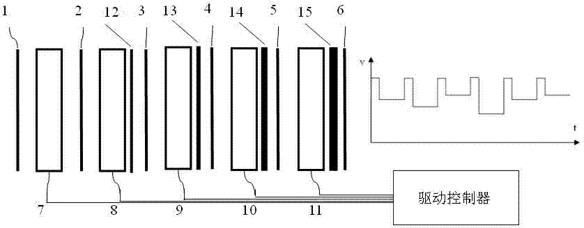
[0020] figure 2 It is a schematic diagram of the structure and drive of the fast spectral scanning liquid crystal tunable filter of the present invention, which shows a liquid crystal tunable filter with a five-stage cascaded structure, which includes six polarizers (1, 2, 3, 4, 5 , 6), 5 electrically controlled liquid crystal wave plates (7, 8, 9, 10, 11) and four fixed phase retarders (12, 13, 14, 15), polarizers, electrically controlled liquid crystal wave plates and fixed phase The retarders are arranged parallel to each other and stacked at intervals, forming a total of five stages, and no fixed phase retarder is added to the first stage. Among them, the directions of transmitted polarized light of all polarizers (1, 2, 3, 4, 5, 6) are parallel to each other, and the directions of fast axes of all electrically controlled liquid crystal wave plates (7, ...


PUM

PropertyMeasurementUnit
thicknessaaaaaaaaaa

Abstract

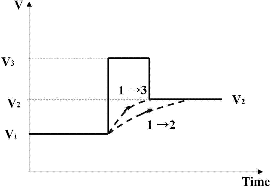
The invention provides a rapid spectrum scanning liquid crystal electric control adjustable optical filter which comprises a liquid crystal adjustable optical filter body and a drive controller. The liquid crystal adjustable optical filter body is of a multistage cascade structure, polarizing films, electric control liquid crystal wave plates and fixed phase retardation films are sequentially and mutually arrayed in parallel and are stacked at intervals to form multiple stages, and the fixed phase retardation films can be arranged or cannot be arranged in the first stage. The transmission polarized light directions of all the polarizing films are mutually in parallel, and an angle of 45 degrees is formed between the fast axis directions of all the electric control liquid crystal wave plates and the transmission polarized light directions of all the polarizing films. In the structure of each stage, the electric control liquid crystal wave plates are controlled by the drive controller, and alternating current overvoltage drive signals of different amplitudes are loaded. The liquid crystal electric control adjustable optical filter has the advantages that rapid spectrum scanning and imaging can be achieved, the spectrum scanning speed can be effectively increased, the spectral imaging frame frequency can be effectively improved, and the applied range of the liquid crystal electric control adjustable optical filter is greatly expanded in the fields of remote sensing detection, medical diagnosis, environmental monitoring, agricultural and forestry general investigation and the like.

Description

technical field [0001] The invention belongs to the technical field of spectral imaging, and in particular relates to a liquid crystal electronically controlled adjustable filter for spectral scanning. Background technique [0002] Compared with filter wheel, interference, dispersion, and acousto-optic tunable spectral imaging devices, spectral imaging devices based on liquid crystal electronically controlled tunable filters have the advantages of small size, light weight, and low power consumption. However, limited by factors such as driving mode and liquid crystal material, its spectral scanning speed is slow, and the spectral imaging frame rate is generally 10-20 frames per second. When the liquid crystal tunable filter has a large aperture, the Conventional drive mode, the response time can generally reach hundreds of milliseconds. For dynamic spectral imaging, the time for spectral imaging system to obtain spectral information is largely restricted, which brings great ...

Claims


Application Information

Patent Timeline
Patent Type & Authority Applications(China)
IPC IPC(8): G02F1/13363G02F1/133G02F1/1347
Inventor 骆永全沈志学龙燕刘仓理赵剑衡吴军张大勇黄立贤
Owner INST OF FLUID PHYSICS CHINA ACAD OF ENG PHYSICS
Learn More