Transverse flux permanent magnet or magnetic reluctance permanent magnet motor of annular box structure

A permanent magnet motor, transverse magnetic flux technology, applied to synchronous motors with stationary armatures and rotating magnets, magnetic circuit shape/style/structure, magnetic circuit stationary parts, etc. and electromagnetic interference, and no technical solutions are given, so as to reduce magnetic flux leakage and harmonic interference, enhance insulation performance, and reduce motor noise.

Inactive Publication Date: 2014-05-14
王新
View PDF1 Cites 2 Cited by
  • Summary
  • Abstract
  • Description
  • Claims
  • Application Information

AI Technical Summary

Problems solved by technology

[0005] Second, the flow direction of the magnetic flux changes from radial to lateral, and the plane where the magnetic force lines are located is turned by 90°, which makes it difficult to directly use the silicon steel sheets that have been widely used in radial flux motors in transverse flux motors.
[0006] Third, in the radial flux induction motor, there are winding ends outside the core slots at the front and rear ends of the stator or rotor, which will generate magnetic flux leakage and electromagnetic interference; in the existing transverse flux motor, due to the stator or The iron cores of the rotor are all discrete, and there are also winding conductors exposed outside the core winding slots at the intervals of the discrete iron cores, which will also generate magnetic flux leakage and electromagnetic interference
The invention only stated a little common knowledge, but did not give a specific technical solution

Method used


Image

  • Transverse flux permanent magnet or magnetic reluctance permanent magnet motor of annular box structure
  • Transverse flux permanent magnet or magnetic reluctance permanent magnet motor of annular box structure
  • Transverse flux permanent magnet or magnetic reluctance permanent magnet motor of annular box structure

Examples


Embodiment Construction

[0057] The present invention will be further described below in conjunction with the accompanying drawings and embodiments.

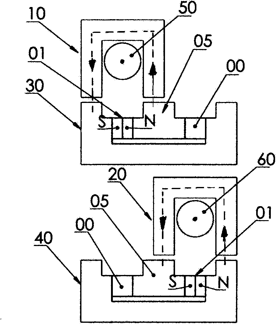
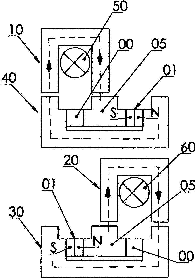
[0058] Firstly, the dynamic corresponding relationship and synchronous switching principle of the odd and even cores of the rotor phase annulus and the odd and even cores of the stator phase annulus and their two 1 / 2 phase windings are explained.

[0059] The number of pole pairs p of the rotor phase ring body core and the stator phase ring body core are equal, and the number of poles 2p is also equal. The rotor phase ring body iron core and the stator phase ring body iron core correspond to each other at equal intervals on both sides of the air gap circumference. Number the rotor phase ring body core and the stator phase ring body core along the circumferential direction, such as figure 1 , figure 2 As shown, the dynamic corresponding relationship and synchronous switching schematic diagram of the odd and even cores of the rotor phase ring body, the...


PUM


Abstract

The invention discloses a transverse flux permanent magnet or magnetic reluctance permanent magnet motor of an annular box structure. The motor is manufactured with a stator phase ring body and a rotor phase ring body as basic components, and an electromagnetism switching mode that iron cores of the stator phase ring body and iron cores of the rotor phase ring body are grouped in an odd and even mode is created. The inside of a left annular box, the inside of a middle annular box and the inside of a right annular box are respectively provided with one odd circumferential array iron core, one even circumferential array iron core and two 1 / 2 phase windings in series connection through the stator phase ring body. The iron cores of the rotor phase ring body are divided into the following two kinds: one kind of the iron cores serves as permanent magnet motors, a permanent magnet is embedded between a left magnetic pole and a middle magnetic pole of each odd iron core, a non-magnetic steel structure body is embedded between the middle magnetic pole and a right magnetic pole of each odd iron core, and vice versa; one kind of the iron cores serves as magnetic reluctance permanent magnet motors, a leftwards middle magnetic pole is embedded in each odd iron core, a non-magnetic steel structure body is embedded between each middle magnetic pole and the corresponding right magnetic pole, a rightward middle magnetic pole is embedded in each even iron core, a non-magnetic steel structure body is embedded between each left magnetic pole and the corresponding middle magnetic pole, and vice versa; the polarity directions of the permanent magnets embedded in the odd iron cores and even iron cores or the polarity directions of the stacked body of the magnetic reluctance permanent magnet materials of the leftward middle magnetic poles and the rightward middle magnetic poles are the same. The stator phase ring body and the rotor phase ring body are coaxially sleeved and are assembled in a segmented mode in the axial direction. The motor has universality.

Description

technical field [0001] The invention relates to a transverse flux permanent magnet or reluctance permanent magnet motor, in particular to a transverse flux permanent magnet or reluctance permanent magnet motor with a ring box structure. Background technique [0002] Because the magnetic circuit and the circuit of the transverse flux permanent magnet motor are perpendicular to each other in space, it overcomes the shortcomings of the magnetic circuit and the circuit of the radial flux motor, that is, the size of the teeth and the slots are mutually restricted on the same cylindrical section, and has the ability to improve the power of the motor. And torque density, easy to realize the characteristics of multi-phase and multi-pole logarithmic structure, it has become a focus of attention and research in the field of motor technology. However, since Professor H. Weh of Germany proposed the concept of transverse flux permanent magnet machine in the 1980s, transverse flux permane...

Claims


Application Information

Patent Timeline
Patent Type & Authority Applications(China)
IPC IPC(8): H02K1/12H02K1/27H02K21/14
Inventor 王新
Owner 王新
Why Eureka
Try Eureka