Stepless grinding and polishing device

A stepless, grinding and polishing technology, applied in the direction of grinding/polishing equipment, grinding machines, grinding machine parts, etc., can solve the problems of dragging tool mark polishing gloss, abrasive tools affecting the surface processing quality of plates, and poor surface quality , to achieve good rough grinding and polishing effect, good polishing effect, and reduce roughness

Inactive Publication Date: 2014-05-21
广东工科机电有限公司
View PDF7 Cites 12 Cited by
  • Summary
  • Abstract
  • Description
  • Claims
  • Application Information

AI Technical Summary

Problems solved by technology

When working, the working method of the coarse grinder with the drum structure is that the abrasive tool is in line contact with the plate, and there are striped grinding marks on the processed surface, and the surface roughness of the plate is relatively large; and the abrasive tool is easily affected by the reverse grinding deformation on the surface of the plate processing quality
The abrasive tool of the swing-foot polishing machine is also a linear contact between the abrasive tool and the plate surface. When polishing, the surface of the plate is prone to dragging marks and uneven polishing gloss.
At the same time, due to the rough surface and poor surface quality of the plate after processing by

Method used


Image

  • Stepless grinding and polishing device
  • Stepless grinding and polishing device
  • Stepless grinding and polishing device

Examples


Embodiment 1

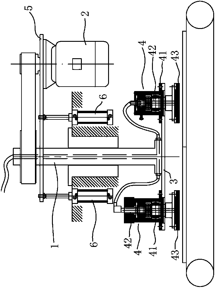
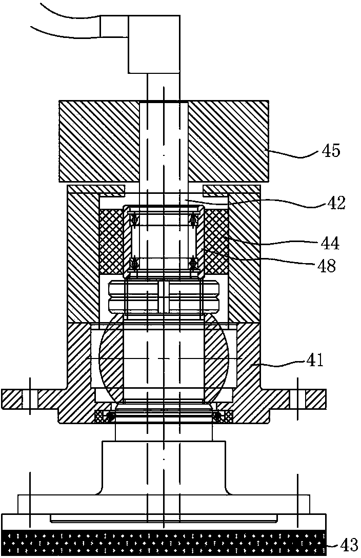
[0029] Embodiment 1, with reference to figure 1 and figure 2 , the balance device includes a balance weight 45 arranged on the upper end of the grinding wheel shaft 42 . The balance counterweight 45 can balance the centrifugal force at both ends of the joint bearing.

Embodiment 2

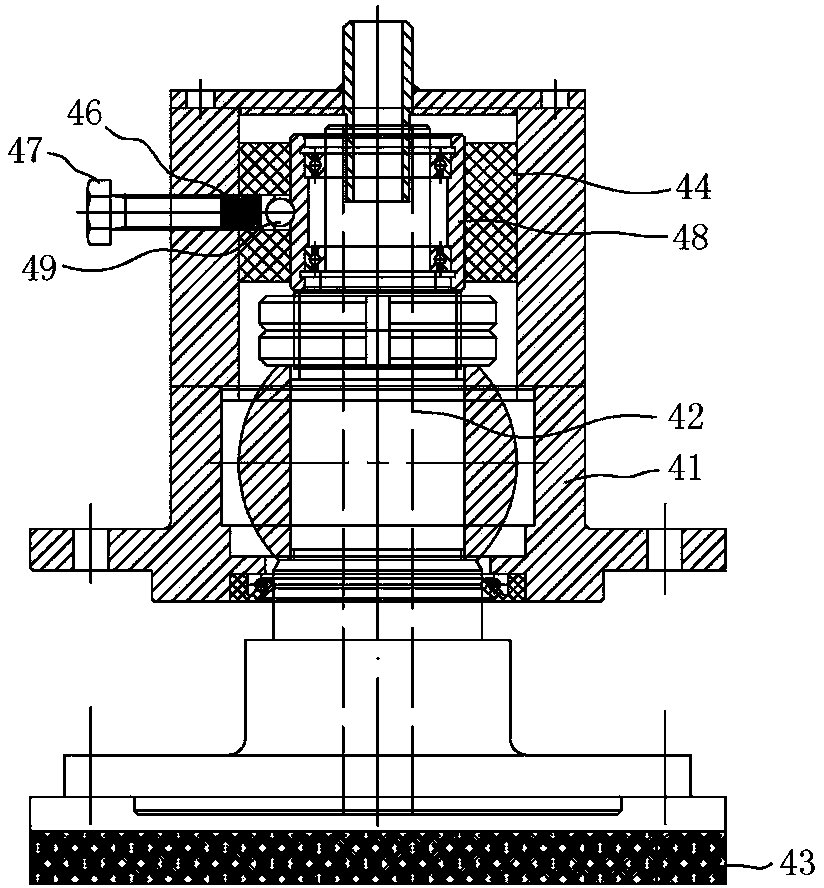
[0030] Embodiment 2, with reference to figure 1 and image 3 , the balance device includes a ball 49 that can be radially adjusted and limited, and directly or indirectly abuts against the upper section of the grinding wheel shaft 42 .

[0031]Specifically, the balance device also includes a radially arranged compression spring 46. The compression spring 46 has a fixed end and a movable end. The direction of the block toward the grinding wheel shaft 42 is a concave spherical surface, and the ball is supported by the concave spherical surface. The fixed end of the compression spring 46 is connected with the compression adjustment screw rod 47 , and the compression adjustment screw rod 47 is screwed with the radial position adjustment screw hole arranged on the grinding head fixing seat 41 . That is to say, the order of the balancing device accessories from outside to inside is: compression adjustment screw rod 47-compression spring 46-the bump with concave spherical surface-b...


PUM


Abstract

The invention discloses a stepless grinding and polishing device. The stepless grinding and polishing device comprises a main shaft and a revolution plate connected to the lower section of the main shaft. A plurality of grinding head installation positions are arranged on the revolution plate. A stepless grinding head is arranged in each grinding head installation position. Each stepless grinding head comprises a grinding head fixing base with a shaking space. Grinding blocks are connected with the lower ends of grinding wheel shafts. The middle sections of the grinding wheel shafts are provided with spherical motion pairs, wherein the spherical motion pairs are located in the shaking spaces, and gaps are reserved between the spherical motion pairs and the peripheral walls of the shaking spaces. The upper sections of the grinding wheel shafts are connected with the grinding head fixing bases in an elastic mode. In the working process, the grinding method that revolution and free rotation are integrated and the grinding blocks can rotate in all directions in the free rotation process is achieved for the stepless grinding heads, and therefore the surface of a plate to be machined can have a certain profiling function, the surface of the plate can not be easily pressed and damaged, the rough grinding and polishing effects are good, and work efficiency is high. The stepless grinding and polishing device is suitable for machining surfaces of building ceramics, stone materials and decorative plates.

Description

technical field [0001] The invention relates to an abrasive tool used for rough grinding and polishing of building ceramics, stone materials and decorative plates. Background technique [0002] Now in the industries of architectural ceramics, stone, decorative plate processing, etc., the rough grinding machine with the saddle frame mounted drum structure is mainly used to roughly grind the plate and the polishing grinding head of the swinging foot type is used for polishing. When working, the working method of the coarse grinder with the drum structure is that the abrasive tool is in line contact with the plate, and there are striped grinding marks on the processed surface, and the surface roughness of the plate is relatively large; and the abrasive tool is easily affected by the reverse grinding deformation on the surface of the plate processing quality. The abrasive tool of the swing-foot polishing machine is also in linear contact with the surface of the plate. When poli...

Claims


Application Information

Patent Timeline
IPC IPC(8): B24B7/22
CPCB24B7/22B24B27/0076B24B41/042
Inventor 龙其瑞黄军蔡永帮
Owner 广东工科机电有限公司
Why Eureka
Try Eureka