
Subwavelength waveguide and preparation method thereof

A sub-wavelength, waveguide technology, applied in the field of semiconductor optoelectronics, can solve problems such as large waveguide area and defects, achieve process compatibility, avoid absorption loss, and compact structure

Active Publication Date: 2016-06-15
南通新微研究院 +1
View PDF3 Cites 0 Cited by
  • Summary
  • Abstract
  • Description
  • Claims
  • Application Information

AI Technical Summary

Problems solved by technology

It is easier to realize a compact sub-wavelength waveguide by using metal surface plasmons. However, due to the absorption of metals for light waves in the communication band and commonly used materials such as gold and silver are not fully compatible with integrated circuit technology, it is not a sub-wavelength waveguide. First choice; photonic crystal sub-wavelength waveguide needs to prepare photonic crystal array, realize line defects in it or use self-collimation principle for beam transmission, overall it leads to too large waveguide area

Method used


Image

  • Subwavelength waveguide and preparation method thereof
  • Subwavelength waveguide and preparation method thereof
  • Subwavelength waveguide and preparation method thereof

Examples


Embodiment Construction

[0027] Embodiments of the present invention are described below through specific examples, and those skilled in the art can easily understand other advantages and effects of the present invention from the content disclosed in this specification. The present invention can also be implemented or applied through other different specific implementation modes, and various modifications or changes can be made to the details in this specification based on different viewpoints and applications without departing from the spirit of the present invention.

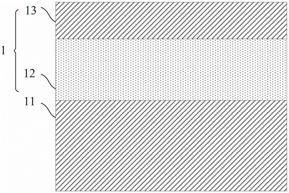
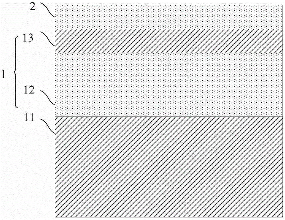
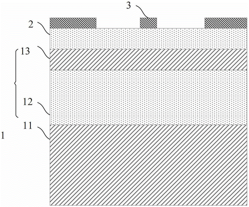
[0028] see Figure 1 to Figure 7 . It should be noted that the diagrams provided in this embodiment are only schematically illustrating the basic idea of ​​the present invention, and only the components related to the present invention are shown in the diagrams rather than the number, shape and shape of the components in actual implementation. Dimensional drawing, the type, quantity and proportion of each component can be changed arb...


PUM


Abstract

The invention provides a sub-wavelength waveguide and a preparation method. First, a hard mask is deposited on the surface of an oxygen-containing substrate; afterwards, a periodical single-row photoresist graph layer is manufactured on the surface of the hard mask; then, a single-row periodical hard mask graph layer is formed using the periodical single-row photoresist graph layer as a mask; and finally, etching is performed on a top layer of the oxygen-containing substrate using the single-row periodical hard mask graph layer as a mask to form a single-row periodical cylinder structure by which sub-wavelength waves can be transmitted. The sub-wavelength waveguide in the invention is compact in structure, and the preparation method is compatible with an integrated circuit technology.

Description

technical field [0001] The invention relates to the field of semiconductor optoelectronics, in particular to a sub-wavelength waveguide and a preparation method. Background technique [0002] As the feature size of silicon integrated circuits decreases, the density of transistors per unit area increases exponentially. In 2020, the manufacturing process with a feature size of about 10nm will be put into mass production, and the transistor density will be 16 times that of 2009. As the characteristic area of ​​the chip becomes smaller, the clock frequency of the signal becomes higher and higher, and the signal's clock synchronization requirements become more and more complex, etc., it will become more and more difficult for the electrical interconnection technology based on copper interconnection to meet the needs of inter-chip communication. The demand for high-density optical communication and optical switching continues to grow. [0003] Due to the advantages of large bandw...

Claims


Application Information

Patent Timeline
Patent Type & Authority Patents(China)
IPC IPC(8): G02B6/13G02B6/136
Inventor 武爱民甘甫烷李浩盛振王曦
Owner 南通新微研究院
Learn More