
Concave pit lithium ion battery current collector as well as manufacturing method and equipment of concave pit lithium ion battery current collector

A lithium-ion battery and current collector technology, applied in the direction of electrode carrier/current collector, etc., can solve the problems of large equipment investment, complex process, and large environmental pollution.

Active Publication Date: 2014-05-21
深圳市旭然电子有限公司
View PDF6 Cites 11 Cited by
  • Summary
  • Abstract
  • Description
  • Claims
  • Application Information

AI Technical Summary

Problems solved by technology

[0009] The above research results have been confirmed that increasing the surface of the current collector can improve the performance of lithium-ion batteries. However, in the methods recorded in the literature, the laser processing of the current collector with blind holes on the surface has a large investment in equipment, high production costs, and high technical requirements for operators. It is difficult to promote the market; the use of chemical corrosion and metal etching to treat the surface of the current collector has the problems of great environmental pollution, complicated process and low production efficiency

Method used


Image

  • Concave pit lithium ion battery current collector as well as manufacturing method and equipment of concave pit lithium ion battery current collector
  • Concave pit lithium ion battery current collector as well as manufacturing method and equipment of concave pit lithium ion battery current collector

Examples


Embodiment Construction

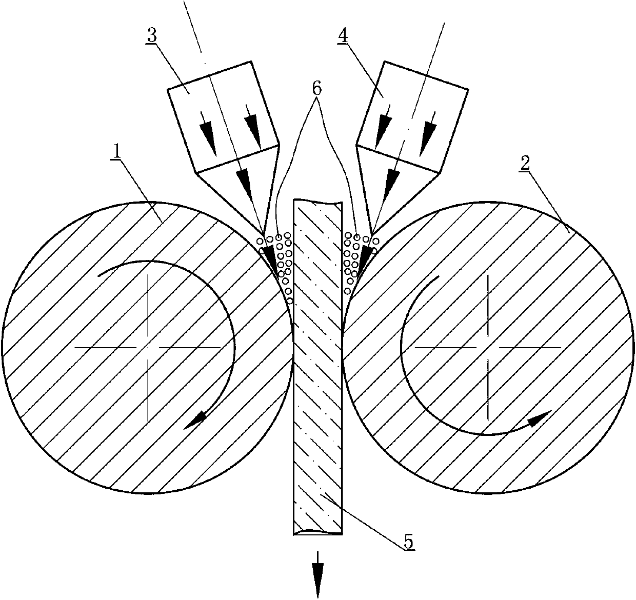
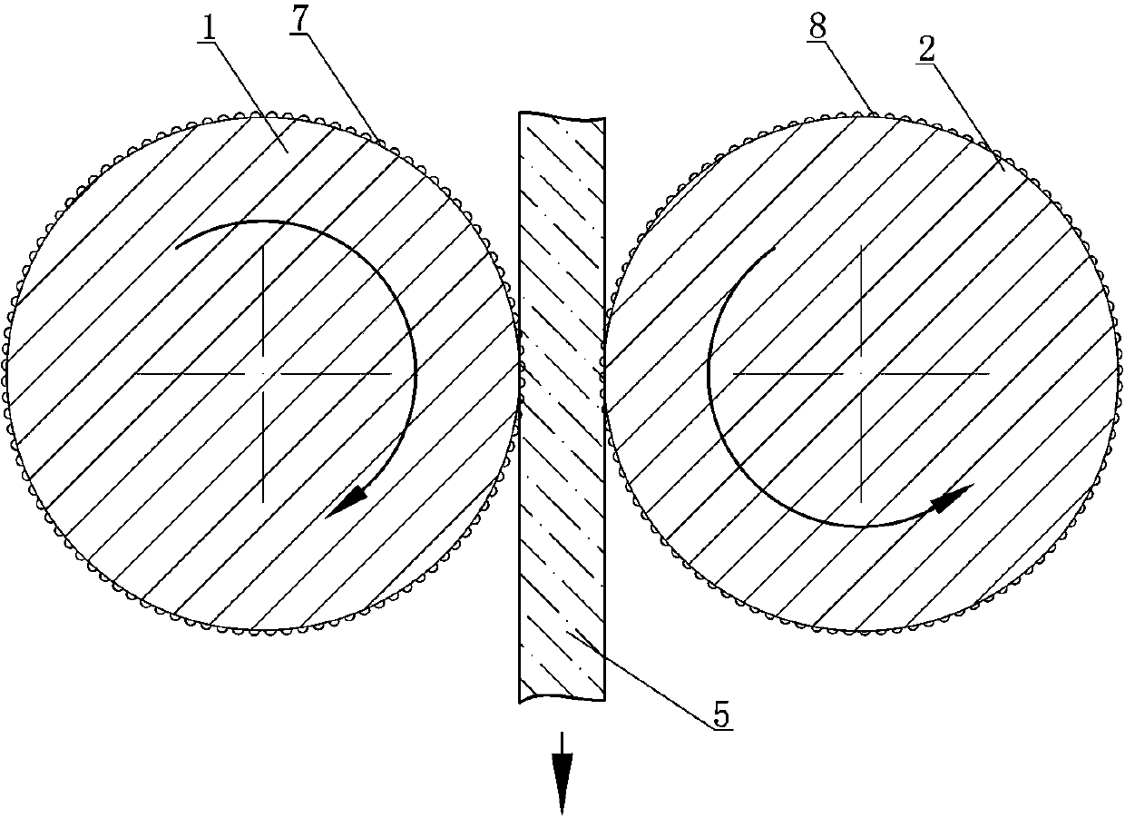
[0033] See figure 1 , the present invention discloses a pitted lithium-ion battery current collector, at least one side of the current collector 5 is provided with pits, and the pits are formed during the process of rolling the current collector by two rolls . figure 1 Among them, the process of the current collector 5 being double-rolled is: when the current collector 5 passes through the rolling station between the left-hand roll 1 and the right-hand roll 2, the left-hand sand filling above the left-hand roll 1 The bucket 2 is filled with particles 6 whose hardness is greater than that of the current collector material between the current collector 5 and the left-hand roll 1. With the extrusion of the left-hand roll 1, the particles 6 form a left side on the left side of the current collector 5. Pit; Certainly, also can or simultaneously the right-hand sand filling bucket 4 above right-hand roll 2 fills the particle 6 that hardness is greater than current collector material...


PUM


Abstract

The invention provides a concave pit lithium ion battery current collector as well as a manufacturing method and equipment of concave pit lithium ion battery current collector. The manufacturing method comprises the following steps: filling the part between the current collector and a leftward roller with grains with the rigidity which is greater than that of a current collector material by a leftward sand filling hopper above the leftward roller when the current collector passes through a rolling station between the leftward roller and a rightward roller; extruding by the leftward roller to form a left concave pit in one side of the current collector by the grains; or / and filling the part between the current collector and the rightward roller with the grains with the rigidity which is greater than that of the current collector material by a rightward sand filling hopper above the rightward roller; and extruding by the rightward roller to form a right concave pit in one side of the current collector by the grains. According to the concave pit lithium ion battery current collector as well as the manufacturing method and equipment of of the current collector, the contact face between an active material of the concave pit lithium ion battery current collector and the surface of the current collector is enlarged and the surface sticking area between the active material and the current collector is enlarged, so that the adhesion strength is easy to enhance and the contact conductivity is improved; a process for manufacturing the concave pit lithium ion battery current collector by using a sand filling and rolling method is simple and is suitable for large-scale industrial production.

Description

technical field [0001] The invention relates to a lithium-ion battery material and its manufacturing method and equipment, in particular to a single-sided or pitted lithium-ion battery current collector and its manufacturing method and equipment. Background technique [0002] Lithium-ion batteries are composed of positive electrode materials, negative electrode materials, current collectors, separators, electrolytes and casings, etc. The current collectors are positive electrode materials and negative electrode material slurry coating attachment carriers, and are also conductor devices for positive electrode materials and negative electrode materials The current collector is usually made of copper foil or aluminum foil. In order to obtain a small contact resistance, the selected copper foil is made of pure copper, and the selected aluminum foil is also made of pure aluminum. With the development of pure electric vehicles, the discharge power of lithium-ion batteries is requi...

Claims


Application Information

Patent Timeline
IPC IPC(8): H01M4/70
CPCH01M4/70Y02E60/10
Inventor 方园郑君邓昌沪
Owner 深圳市旭然电子有限公司
Learn More