Cutting method of liquid crystal panel, and liquid crystal panel
A liquid crystal panel, cutting method technology, applied in glass cutting device, optics, glass manufacturing equipment and other directions
- Summary
- Abstract
- Description
- Claims
- Application Information
AI Technical Summary
Problems solved by technology
Method used
Image

Examples
Embodiment 1
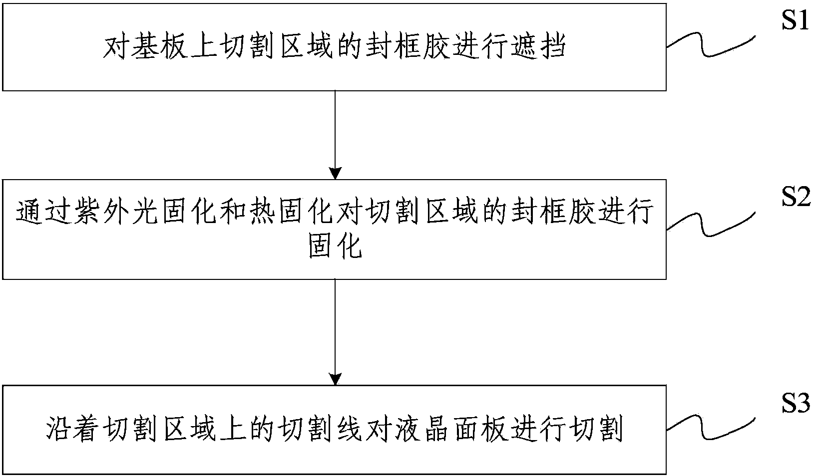
[0038] Embodiment 1 of the present invention provides a cutting method of a liquid crystal panel, and the steps are as follows: figure 2 shown, including:
[0039] Step S1, shielding the frame sealant in the cutting area on the substrate;
[0040] Step S2, curing the frame sealant in the cutting area by UV curing and heat curing;
[0041] Step S3, cutting the liquid crystal panel along the cutting line on the cutting area.
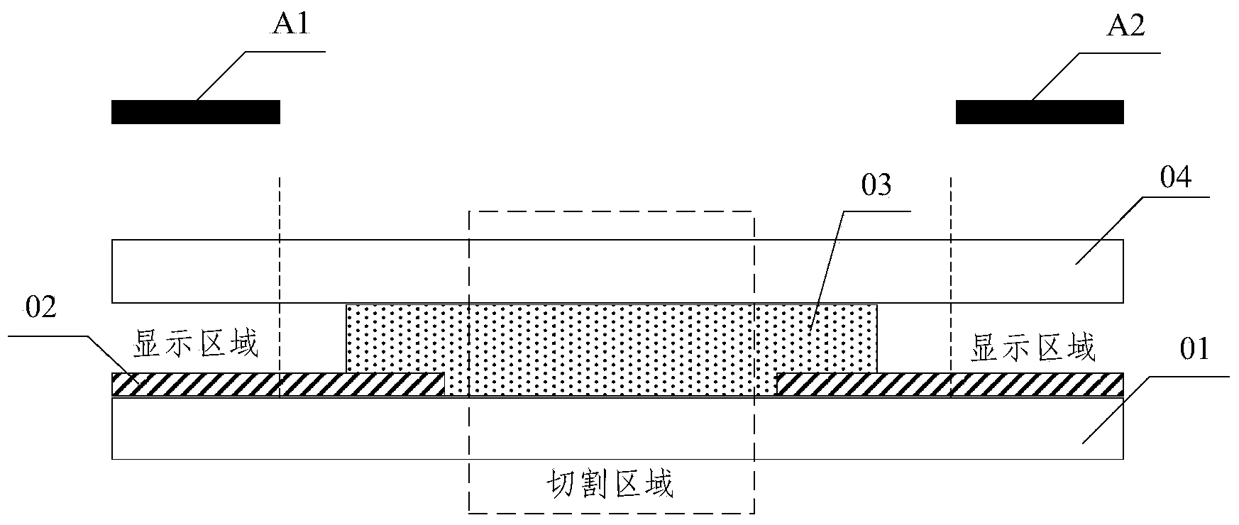
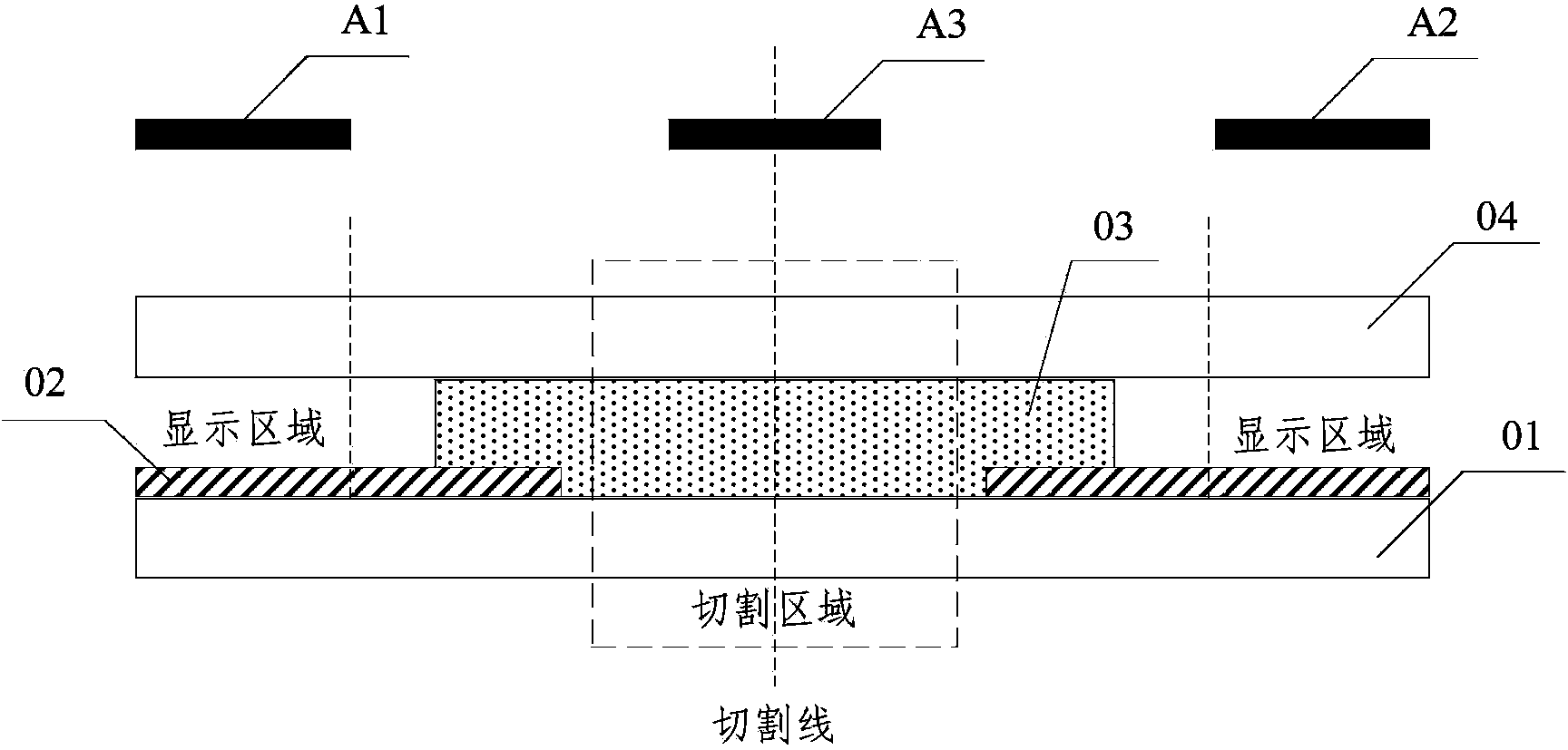
[0042] In the prior art, after the frame sealant is fully cured, it is necessary to use the complex cutting process of cutter wheel cutting and laser cutting. During the cutting process, there will be poor cutting due to the sealant covering the cutting line, but this embodiment passes Covering the sealing glue in the cutting area, reducing the curing rate of the sealing glue in the cutting area, can avoid the bad splits during cutting, only need to use the knife wheel to cut, no need for laser cutting, and reduce the operation of the cutting process C...
Embodiment 2
[0052] Embodiment 2 of the present invention also provides a method for cutting a liquid crystal panel. The steps are the same as in Embodiment 1, but the difference from Embodiment 1 is that in this embodiment, the blocking of the sealant in the cutting area on the substrate specifically includes :
[0053] The shielding layer 20 is fabricated on the cutting line on the substrate, the shielding layer 20 is located outside the sealant 10 , and the cutting line is located at the center of the shielding layer 20 .
[0054] The schematic diagram of the above design is as Figure 5 As shown, the middle area is the display area X of the liquid crystal panel, the outer side of the display area X is a circle of sealant 10, and the outer circle is a circle of shielding layer 20, which plays the role of blocking ultraviolet light.
[0055] Preferably, in this embodiment, the shielding layer 20 is an opaque resin, which may be a black matrix (Black Matrix, BM for short), or other resin...
Embodiment 3
[0061] Embodiment 3 of the present invention also provides a liquid crystal panel obtained based on the cutting method provided in Embodiment 1 above, including a first substrate and a second substrate, and the sealant in the cutting area of the first substrate or the second substrate is blocked .
[0062] Specifically include:
[0063] A light baffle is arranged above the cutting area for blocking ultraviolet light, the width of the light baffle is larger than that of the cutting area, and the center of the light baffle coincides with the center of the cutting area.
[0064] Wherein, the width of the light blocking plate is 0.15 mm to 0.25 mm.
PUM
| Property | Measurement | Unit |
|---|---|---|
| Width | aaaaa | aaaaa |
Abstract
Description
Claims
Application Information
 - R&D
- Intellectual Property
- Life Sciences
- Materials
- Tech Scout
- Unparalleled Data Quality
- Higher Quality Content
- 60% Fewer Hallucinations
Browse by: Latest US Patents, China's latest patents, Technical Efficacy Thesaurus, Application Domain, Technology Topic, Popular Technical Reports.
© 2025 PatSnap. All rights reserved.Legal|Privacy policy|Modern Slavery Act Transparency Statement|Sitemap|About US| Contact US: help@patsnap.com