Solar photovoltaic cable

A solar photovoltaic and cable technology, which is applied in the direction of insulated cables, power cables, cables, etc., can solve the problems of unsatisfactory, restricted, increased R&D costs and production costs, etc., and achieve the effect of long service life and high electrical insulation

Inactive Publication Date: 2014-05-28
QINGDAO YUTAI NEW ENERGY SCI & TECH
View PDF0 Cites 1 Cited by
  • Summary
  • Abstract
  • Description
  • Claims
  • Application Information

AI Technical Summary

Problems solved by technology

However, in actual production and application, in order to meet the relevant standards of UL, it is impossible to meet the requirements of TUV Rheinland's technical specification 2PfG 1169 / 08.2007, because the main indicators of UL's relevant standards are flame retardancy and insulation, and the main indicators of TUV It is cable life, heat aging and halogen-free. However, there is no material in the world as an insulating layer that can meet the requirements of UL and TUV at the same time. Therefore, if the product can only meet one requirement, it will limit the sales area of ​​the product.
Therefore, the same photovoltaic cable product cannot be sold in the two major markets at the same time, or two different products can only be sold separately for the two major markets, which not only increases the R&D cost and production cost of the enterprise, but also is not conducive to the research and development of photovoltaic modules
Solar photovoltaic cables are mainly used in the junction box of solar photovoltaic modules. The major companies in the world that produce junction boxes are improving the existing junction boxes, especially reducing the size and weight of the junction box. Due to solar photovoltaic cables It is one of the main components of the junction box, so the outer diameter and weight of the existing solar photovoltaic cables directly restrict the improvement of the junction box

Method used


Image

  • Solar photovoltaic cable
  • Solar photovoltaic cable

Examples


Embodiment Construction

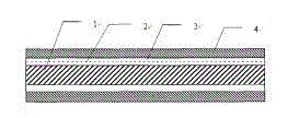
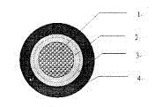
[0031] Such as figure 1As shown, the solar photovoltaic cable mainly includes a conductor 1, a sheath 4, an inner insulation layer 2 and an outer insulation layer 3. Linked polyolefin material, the outer insulating layer 3 adopts extruded low-smoke, halogen-free, flame-retardant irradiation cross-linked polyolefin ring material from -40°C to 125°C, they are adhered and not easy to separate, and the inner insulating layer and the outer insulating layer The layer adopts high-precision machine head and non-adjustable tungsten steel mold, double-head co-extrusion, online infrared dynamic outer diameter tester and online dynamic core eccentricity tester, which ensure the stability of production and product quality, and effectively reduce production costs. Among them, the internal insulation adopts a volume resistance of 1.0×10¹⁴ ~ 9.0×10¹⁷Ω cm at 20°C; apply a 600V sine wave voltage of 48 ~ 62HZ, soak in water at 90°C for more than 12 weeks, and the minimum insulation resistance pe...


PUM

PropertyMeasurementUnit
thicknessaaaaaaaaaa
thicknessaaaaaaaaaa
thicknessaaaaaaaaaa

Abstract

The invention belongs to the field of a cable and especially provides a solar photovoltaic cable applied to a photovoltaic solar system. The solar photovoltaic cable mainly comprises a conductor, an insulating layer and a sheath. The insulating layer comprises an inner insulating layer and an outer insulating layer. The inner insulating layer is made of a -40 DEG C-125 DEG C low-smoke zero-halogen radiation cross-linking polyolefin material, of which the volume resistance is 1.0*1014-9.0*1017 Omega.cm when the temperature is 20 DEG C. The outer insulating layer is made of a -40 DEG C-125 DEG C low-smoke zero-halogen anti-flaming radiation cross-linking polyolefin material, of which the volume resistance is 1.0*1012-9.0*1015 Omega.cm when the temperature is 20 DEG C and the oxygen index is 24-46. The thickness of the inner insulating layer is 0.1 mm-1.3 mm. The thickness of the outer insulating layer is 0.2 mm-1.3 mm. The advantages lie in that the external diameter of the finished product is reduced by 16.7%; weight is reduced by 49.1%; the decrease amount of the thickness of the insulating layer is 42.5% of the prior art; working performances, such as acid and alkali resistance, humidity and heat resistance, ozone resistance and ultraviolet resistance and the like are improved; and the service life of the cable is prolonged.

Description

technical field [0001] The invention belongs to the field of cables, in particular to a solar photovoltaic cable applied to a photovoltaic solar energy system. Background technique [0002] Energy is the basic resource that human beings rely on for survival and development. With the progress of society and the development of science and technology, the consumption of conventional resources is increasing day by day, but the reserves of available energy are decreasing. The inexhaustible and inexhaustible green energy --- solar energy has aroused great interest of people. [0003] In the 21st century, in order to promote the development of the solar energy industry, the governments of various countries, especially Europe, have adopted a series of incentive policies such as government subsidies and funding. Coupled with the increasing awareness of environmental protection, the solar energy industry is increasing at a rate of about 40%, and will continue to grow in the next few y...

Claims


Application Information

Patent Timeline
Patent Type & Authority Applications(China)
IPC IPC(8): H01B7/02H01B7/295H01B7/17H01B9/00
Inventor 徐洪寿
Owner QINGDAO YUTAI NEW ENERGY SCI & TECH
Why Eureka
Try Eureka