
Reverse osmosis-based high-concentration sewage treatment method

A sewage treatment method and reverse osmosis technology, applied in the direction of osmosis/dialysis water/sewage treatment, water/sewage multi-stage treatment, water/sludge/sewage treatment, etc., can solve the problem of hydraulic explosive diffusion, short service life of equipment, Unstable effluent effect and other problems, to achieve the effect of reducing membrane fouling, prolonging life, and reducing fouling on the membrane surface

Active Publication Date: 2014-06-11
湖南北控威保特环境科技股份有限公司
View PDF8 Cites 10 Cited by
  • Summary
  • Abstract
  • Description
  • Claims
  • Application Information

AI Technical Summary

Problems solved by technology

However, in the prior art disc-tube reverse osmosis (DTRO) membrane system, the surface of the diversion plate is provided with a bump-like structure as a diversion structure, such as Figure 7 As shown, this structure is easy to cause explosive diffusion of hydraulic power, resulting in increased energy loss of the system; and the shape of the diaphragm is circular, such as Figure 8 As shown, it is easy to cause excessive local pressure to cause the diaphragm to be penetrated and damaged
[0003] In general, affected by different factors, the membrane treatment devices in the prior art have high energy consumption, low water production rate, unstable water discharge effect and short service life of the equipment during operation. Limited by these defects, Membrane treatment technology has certain bottlenecks when it is applied to the treatment of high-concentration sewage such as landfill leachate

Method used


Image

  • Reverse osmosis-based high-concentration sewage treatment method
  • Reverse osmosis-based high-concentration sewage treatment method
  • Reverse osmosis-based high-concentration sewage treatment method

Examples


Embodiment

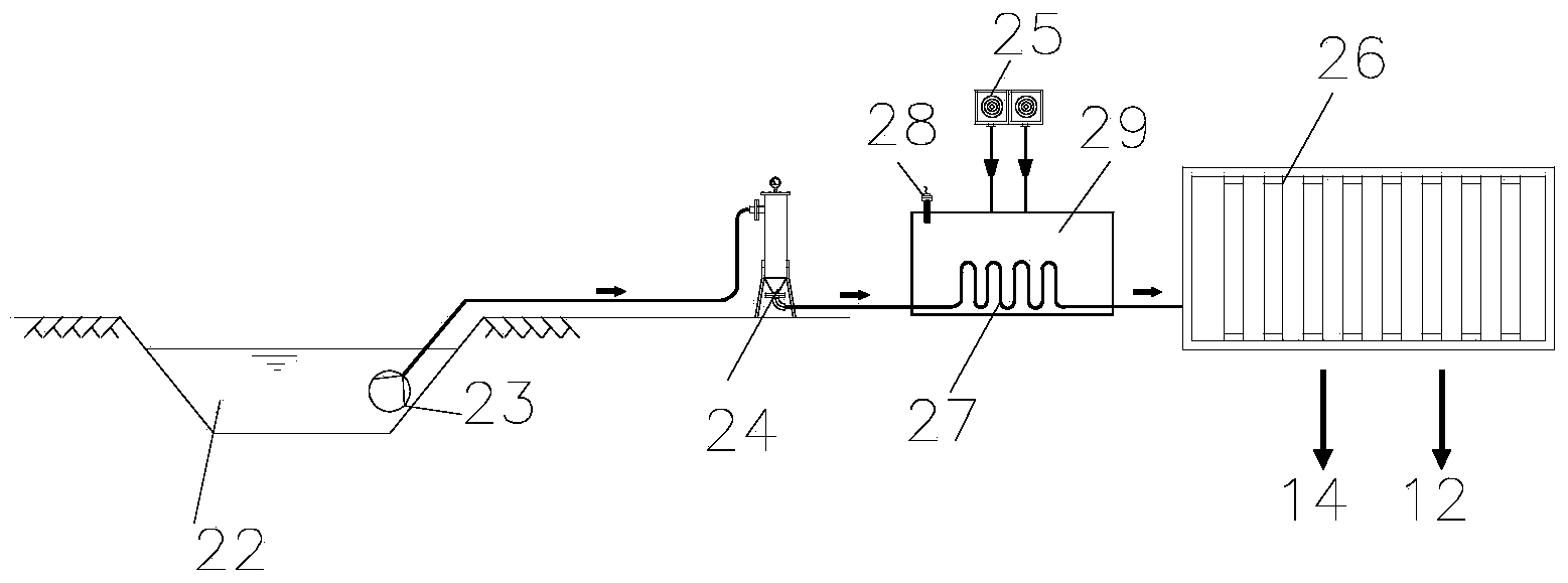
[0049] Such as figure 1 Shown, a kind of processing method of the landfill leachate based on reverse osmosis of the present invention, the method may further comprise the steps:

[0050] (1) Pre-filtering treatment:

[0051] Such as figure 1 As shown in , a leachate lifting pump 23 is installed in the leachate regulating tank 22, and the landfill leachate to be treated enters the filter 24 through the lift pump 23, and the large particles in the raw water of the landfill leachate are removed in the filter 24 And impurities are filtered out to ensure less impurities in landfill leachate.

[0052] (2) Preheating treatment:

[0053] The pre-filtered landfill leachate is transported to the pre-heating device 25 through pipelines for pre-heating treatment; Heat, the preheated heat transfer medium circulates in the heating pipe 27, transfers heat to the landfill leachate in the leachate preheating pool 29, and the leachate preheats the pool through the temperature controller 2...


PUM


Abstract

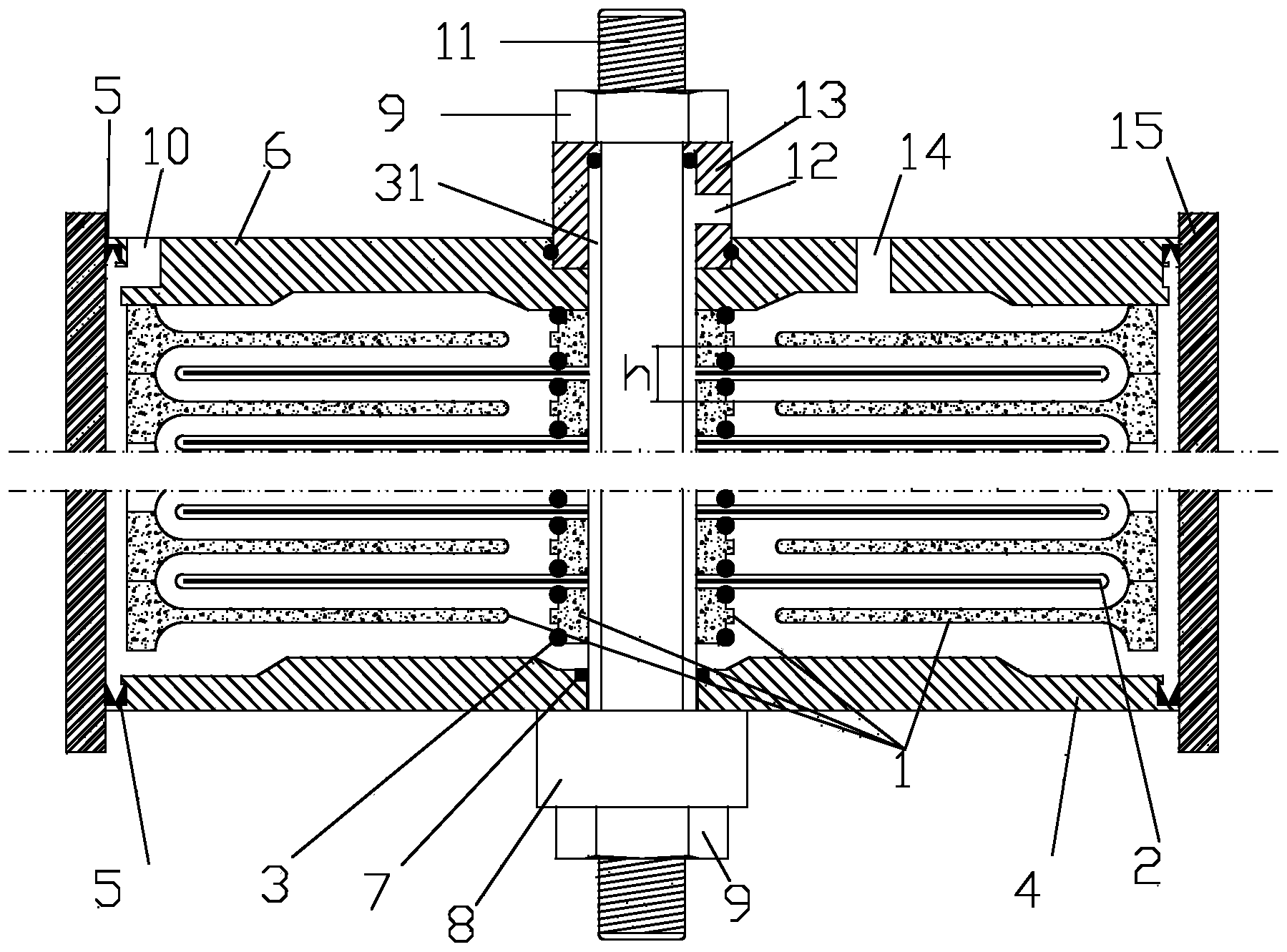
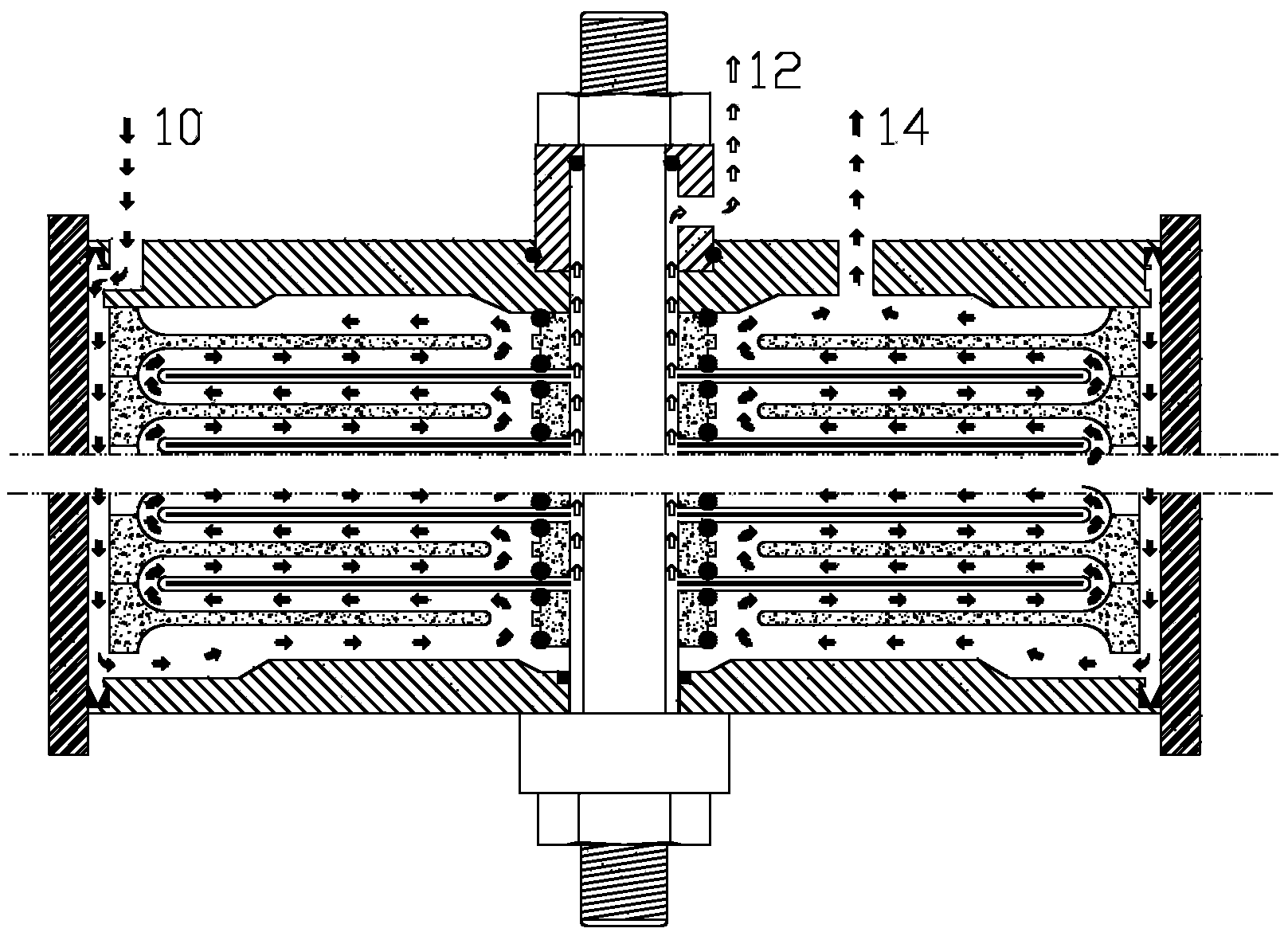
The invention discloses a reverse osmosis-based high-concentration sewage treatment method. The reverse osmosis-based high-concentration sewage treatment method comprises the following steps of firstly pre-filtering and pre-heating the sewage; carrying out the reverse osmosis treatment on the preheated sewage; feeding the preheated sewage to the bottom of a reverse osmosis treatment device; feeding the sewage on the bottom into a primary sewage laminar flow passage through an elongated distributing hole, dispersing the sewage to the periphery of a laminar flow disc through a spoke-shaped guide passage arranged on the surface of the laminar flow disc, enabling the sewage to upwards reversely enter the other side of the passage when the sewage flows to the edge of the laminar flow disc, then converging the sewage onto a central hole, enabling the sewage to upwards reversely enter a secondary sewage laminar flow passage through the elongated distribution hole, circulating the sewage to form a radiated S-shaped route from bottom to top, and finally discharging the sewage through a concentrated liquid discharging port; a water purification component permeates a reverse osmosis membrane of a filter membrane assembly to be conveyed to a permeate liquid outlet to be discharged. The reverse osmosis-based high-concentration sewage treatment method has the advantages of high sewage treatment efficiency, high water yield, low energy consumption, long service life of the filter membrane and the like.

Description

technical field [0001] The invention belongs to the field of high-concentration sewage treatment, and in particular relates to a high-concentration sewage treatment method based on reverse osmosis developed by utilizing the principles of hydrodynamics and hydraulics. Background technique [0002] In recent years, many new technologies have achieved rapid development in the application of high-concentration sewage treatment, such as landfill leachate treatment. One of the current application trends is the application of membrane technology, including microfiltration membranes, ultrafiltration membranes, nanofiltration membranes and reverse osmosis membranes. The advantage of using membrane technology is that the effluent water quality is better and can meet higher discharge requirements. However, in the prior art disc-tube reverse osmosis (DTRO) membrane system, the surface of the diversion plate is provided with a bump-like structure as a diversion structure, such as Figur...

Claims


Application Information

Patent Timeline
Patent Type & Authority Applications(China)
IPC IPC(8): C02F9/10C02F1/44
CPCY02W10/37
Inventor 舒淼高青松刘阳
Owner 湖南北控威保特环境科技股份有限公司
Learn More