Optical correlator based on modal dispersion

An optical correlator and modal dispersion technology, which is applied in the field of optical correlators, can solve the problems of expensive equipment, poor signal-to-noise ratio at the output end of the system, and narrow bandwidth of laser light sources, so as to save costs, overcome selection difficulties, and reduce energy consumption. Effect

Inactive Publication Date: 2014-06-11
BEIJING JIAOTONG UNIV
View PDF2 Cites 4 Cited by
  • Summary
  • Abstract
  • Description
  • Claims
  • Application Information

AI Technical Summary

Problems solved by technology

The bandwidth of the laser light source is narrow, but the laser is expensive. When realizing the correlation detection of multi-bit symbol data streams, the number of lasers required is correspondingly increased, resulting in expensive equipment; LEDs are cheap, but when they are used, they need to be The LED light source is subjected to band-limiting processing through a filter with limited bandwidth, resulting in a poor signal-to-noise ratio at the output of the system
Therefore, the optical correlator based on chromatic dispersion has certain difficulties in the selection of light source

Method used


Image

  • Optical correlator based on modal dispersion
  • Optical correlator based on modal dispersion
  • Optical correlator based on modal dispersion

Examples


Embodiment Construction

[0016] The following will clearly and completely describe the technical solutions in the embodiments of the present invention with reference to the accompanying drawings in the embodiments of the present invention. Obviously, the described embodiments are only some, not all, embodiments of the present invention. Based on the embodiments of the present invention, all other embodiments obtained by persons of ordinary skill in the art without making creative efforts belong to the protection scope of the present invention.

[0017] The present invention will be further described below in conjunction with the accompanying drawings and embodiments.

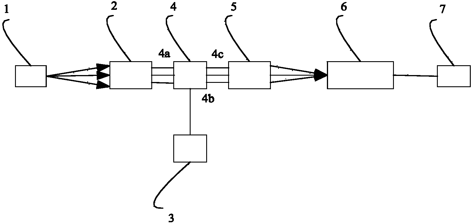
[0018] figure 1 The shown optical correlator based on modal dispersion includes: a light source 1, a first converging lens 2, a signal source 3, a spatial light modulator 4, a second converging lens 5, a multimode optical fiber 6 and a photodetector 7, wherein the light source 1 is located at the focus position of the first converging ...


PUM


Abstract

The embodiment of the invention provides an optical correlator based on modal dispersion, and belongs to the field of optical fiber communication. The optical correlator based on modal dispersion is characterized in that a light source (1) is located at the focal position of a convergent lens (2), the back of the convergent lens (2) is a light input port (4a) of a spatial light modulator (4), an electric input port (4b) of the spatial light modulator (4) is connected with a signal source (3), the back of a light output port (4c) of the spatial light modulator is a convergent lens (5), the focal position of the convergent lens is the input end of a multi-mode optical fiber (6), and the output end of the multi-mode optical fiber (6) is connected with a photoelectric detector (7). The optical correlator based on modal dispersion is basically characterized in that the modal dispersion of the multi-mode optical fiber is used for manufacturing the correlator and has the advantage of being simple in structure, and the optical fiber is short, so that the energy loss in the transmission process of light signals is reduced. The light source bears the signals to be detected, the use of a high-speed modulator is avoided, and system cost is avoided. The use of the multi-mode light source overcomes the defect that an existing optical correlator based on modal dispersion has a high requirement for the bandwidth of the light source, and the optical correlator based on modal dispersion has broad application prospects on the aspect of light signal processing.

Description

technical field [0001] The invention relates to an optical correlator based on mode dispersion, which belongs to the technical field of optical fiber communication system and optical signal processing. Background technique [0002] The optical correlator based on fiber dispersion is a new type of optical signal processing technology. Faced with the increasing transmission rate of optical communication systems and the use of packet switching networks, optical related detection technologies will play an important role in future communication systems. At present, optical correlators based on optical fibers mainly include optical correlators based on fiber Bragg gratings, optical correlators based on fiber delay lines, optical correlators based on optical logic gates, and optical correlators based on chromatic dispersion. The optical correlator based on the fiber delay line needs to have precise delay control, so there are certain difficulties in the length selection of the del...

Claims


Application Information

Patent Timeline
Patent Type & Authority Applications(China)
IPC IPC(8): H04B10/2513H04B10/2581
Inventor 谭中伟秦凤杰李卡
Owner BEIJING JIAOTONG UNIV
Why Eureka
Try Eureka