Alumina forming bimetallic tube for refinery process furnaces and method of making and using

A bimetallic tube, aluminum oxide technology, applied in chemical instruments and methods, petroleum industry, manufacturing tools, etc., can solve problems such as poor mechanical integrity, thermal stability, and low reliability

Inactive Publication Date: 2014-06-11
EXXON RES & ENG CO
View PDF5 Cites 3 Cited by
  • Summary
  • Abstract
  • Description
  • Claims
  • Application Information

AI Technical Summary

Problems solved by technology

However, as is characteristic of all such relatively thin coatings, such coatings exhibit poor mechanical integrity and the

Method used


Image

  • Alumina forming bimetallic tube for refinery process furnaces and method of making and using
  • Alumina forming bimetallic tube for refinery process furnaces and method of making and using
  • Alumina forming bimetallic tube for refinery process furnaces and method of making and using

Examples


Embodiment 1

[0077] Example 1: Crack-free alumina-forming bimetallic tube made of 9Cr (T9) low chromium steel

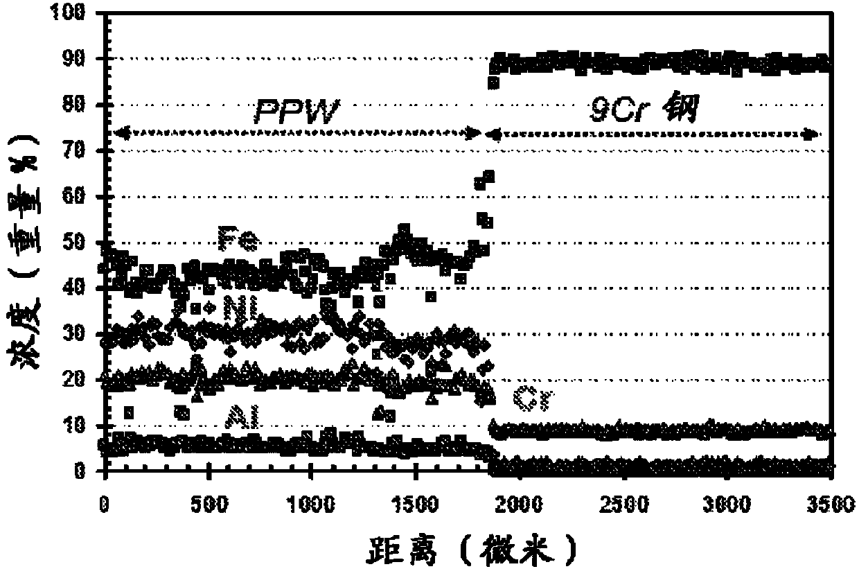
[0078] A short section of 9Cr(T9) furnace tube with dimensions 5.00”OD x 4.25”ID x 12.0”L was prepared and the inner surface of the tube was machined for the PPW process. Alumina forming PPW was prepared by argon atomization Powder "M". The powder is sieved to a size for easy flow during the PPW process. The chemical composition of the powder "M" in % by weight is the balance Ni:22.93Cr:6.68Al:33.76Fe: 0.36 Si. Bimetallic tubes were produced by applying powder "M" to the inner surface of a 9Cr furnace tube by the PPW method.

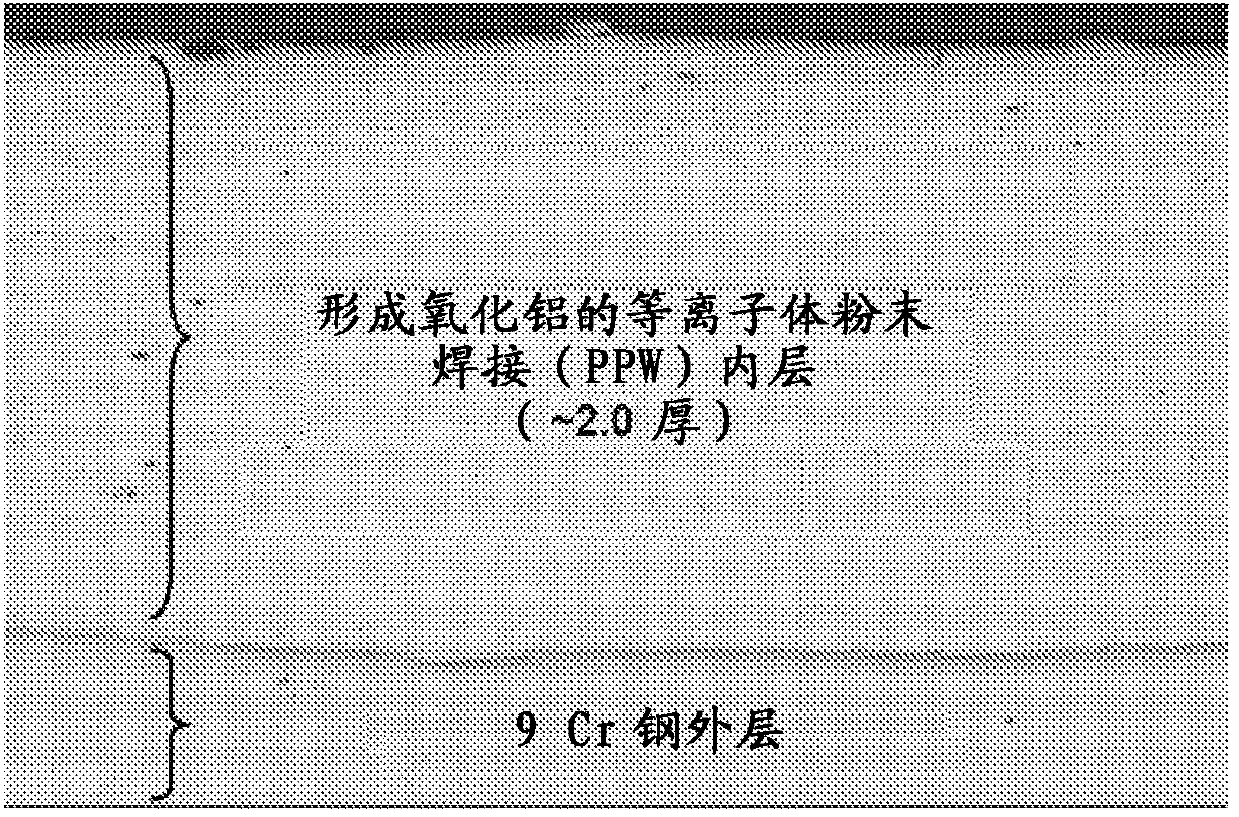
[0079] The resulting bimetallic tube consisted of: i) an outer tube layer of 9.5 mm thick T9 low chromium steel; ii) a 2.0 mm thick inner tube layer formed of aluminum oxide forming alloy lumps; and iii) on the surface of the inner tube layer A 50 nm thick native alumina film was formed. A cross-sectional view of a bimetallic tube revealing the 9Cr stee...

Embodiment 2

[0081] Example 2: Crack-free alumina-forming bimetallic tube made of 9Cr (T9) low chromium steel

[0082] A short section of 9Cr(T9) furnace tube with dimensions 5.00”OD x 4.25”ID x 12.0”L was prepared and the inner surface of the tube was machined for the PPW process. Alumina forming PPW was prepared by argon atomization Powder "O". The powder is sieved to a size for easy flow during the PPW process. The chemical composition of the powder "O" in % by weight is the balance Ni:24.20Cr:6.25Al:32.20Fe: 0.14 Si. Powder "O" was applied to the inner surface of the 9Cr furnace tube by the PPW method, thereby manufacturing a bimetallic tube.

[0083] The resulting bimetallic tube consisted of: i) an outer tube layer of 9.5 mm thick T9 low chromium steel; ii) a 2.0 mm thick inner tube layer formed of aluminum oxide forming alloy lumps; and iii) on the surface of the inner tube layer A 50 nm thick native alumina film was formed. A cross-sectional view of a bimetallic tube revealing ...

Embodiment 3

[0085] Example 3 (comparative example): Cracked aluminum oxide-forming bimetal made of 9Cr (T9) low chromium steel Metal tube

[0086] A short section of 9Cr(T9) furnace tube with dimensions 5.00”OD x 4.25”ID x 12.0”L was prepared and the inner surface of the tube was machined for the PPW process. Alumina forming PPW was prepared by argon atomization Powder "N". The powder is sieved to a size for easy flow during the PPW process. The chemical composition of the powder "N" in % by weight is the balance Ni:19.82Cr:7.36Al:39.30Fe: 0.25 Si. Bimetallic tubes were fabricated by applying powder "N" to the inner surface of a 9Cr furnace tube via the PPW method.

[0087] The resulting bimetallic tube consisted of: i) an outer tube layer of 9.5 mm thick T9 low chromium steel; ii) a 2.0 mm thick inner tube layer formed of aluminum oxide forming alloy lumps; and iii) on the surface of the inner tube layer A 50 nm thick native alumina film was formed. A cross-sectional view of a bime...


PUM

PropertyMeasurementUnit
Thicknessaaaaaaaaaa

Abstract

Provided is a bimetallic tube for transport of hydrocarbon feedstocks in refinery process furnaces, and more particularly in furnace radiant coils, including: i) an outer tube layer being formed from stainless steels including chromium in the range of 15.0 to 26.0 wt.% based on the total weight of the stainless steel; ii) an inner tube layer being formed from an alumina forming bulk alloy including 5.0 to 10.0 wt.% of AL 20.0 wt.% to 25.0 wt.% Cr, less than 0.4 wt.% Si, and at least 35.0 wt.% Fe with the balance being Ni, wherein the inner tube layer is formed plasma powder welding the alumina forming bulk alloy on the inner surface of the outer tube layer; and iii) an oxide layer formed on the surface of the inner tube layer, wherein the oxide layer is substantially comprised of alumina, chromia, silica, mullite, spinels, or mixtures thereof. Also provided are methods of making and using the bimetallic tube.

Description

technical field [0001] The present invention provides compositions, methods of manufacture and methods of use of bimetallic tubes for transporting hydrocarbon feedstocks in refinery process furnaces, more particularly in radiant section furnace tubes of furnaces, to mitigate corrosion, coking and fouling. Background technique [0002] In a typical refinery process, as the first step in the refinery process, contaminants such as sand, salt, and water are removed from stored heavy crude oil by passing through a desalination unit. The clean crude feed is then heated by passing the desalted crude through a series of heat exchangers. The crude oil is then passed through a furnace, which heats the crude oil to a higher temperature. The furnace can be a furnace or an electric furnace fueled by oil, natural gas or refinery fuel gas, and the oil is heated and the oil is injected into the atmospheric distillation column. Extreme heat causes the physical breakdown of crude oil into c...

Claims


Application Information

Patent Timeline
IPC IPC(8): F27B5/14
CPCB23K2203/20F16L9/02C10G75/00B23K10/027B01J19/0026B01J19/02B01J19/2415B01J2219/0218B01J2219/0236B01J2219/0286B22F5/106B22F7/08B23K35/0244B23K35/3033B32B1/08B32B15/011B32B15/015B32B15/18B32B15/20B32B2307/538B32B2307/714B23K2103/20C10G9/203C22C19/05C22C19/058C22C30/00C22C30/02C22C30/04C22C33/0285C22C38/02C22C38/06C22C38/18C22C38/22C22C38/38C22C38/40C23C24/103C23C28/04
Inventor 全昌旻D·S·多伊彻V·A·麦克雷J·E·菲德B·A·赖希
Owner EXXON RES & ENG CO
Why Eureka
Try Eureka