A kind of negative cover material of mercury-free button battery and its preparation method
A button battery and negative electrode cover technology is applied to the negative electrode cover material of mercury-free button battery and the preparation thereof, the negative electrode cover material of mercury-free alkaline zinc-manganese button battery and the field of preparation thereof, and can solve the problem of sticky abrasive tools and coating layers. problems such as falling off
- Summary
- Abstract
- Description
- Claims
- Application Information
AI Technical Summary
Problems solved by technology
Method used
Image
Examples
Embodiment 1
[0066] The specific preparation process of the above-mentioned steel strip: select the SPCC cold-rolled low-carbon steel strip with a thickness of 0.25 mm produced by Shanghai Baosteel as the electroplating substrate. Its chemical composition is (% represents percentage by weight):
[0067]
[0068]
[0069] 1. Treat the low carbon steel strip before plating
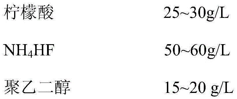
[0070] In order to have a good bond between the coating and the substrate, the cathode substrate must be carefully pretreated before electroplating. Since the surface of the low-carbon steel strip used is relatively flat, there is no need for grinding and mechanical polishing before nickel plating, and degreasing and activation treatment are directly carried out. The method of chemical high-temperature degreasing and electrolytic degreasing is adopted. After the degreasing is complete, the surface of the sample is rinsed with distilled water, and then placed in an activator for activation. After taking out the sa...
Embodiment 2
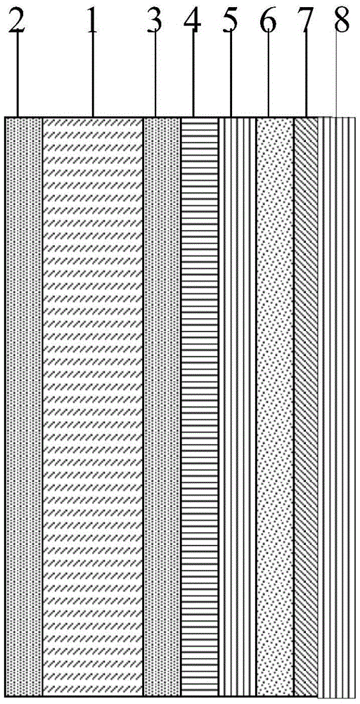
[0152] Preparation method: select the same substrate as in Example 1, adopt the same pre-plating treatment as in Example 1, and electroplate nickel coating, copper coating, first zinc coating, tin coating, indium coating and second zinc coating according to the method of Example 1 respectively. plating, wherein the thickness of the nickel plating layer is 0.3 μm, the thickness of the copper plating layer is 1.5 μm, the thickness of the first zinc plating layer is 0.5 μm, the thickness of the tin plating layer is 3 μm, the thickness of the indium plating layer is 0.1 μm, the thickness of the second zinc plating layer is 1.5 μm, and then the Same heat treatment and mechanical rolling as in Example 1.
Embodiment 3
[0160] Preparation method: select the same substrate as in Example 1, adopt the same pre-plating treatment as in Example 1, and electroplate nickel coating, copper coating, first zinc coating, tin coating, indium coating and second zinc coating according to the method of Example 1 respectively. The plating layer, wherein the thickness of the nickel plating layer is 1.0 μm, the thickness of the copper plating layer is 2.5 μm, the thickness of the first zinc plating layer is 2 μm, and the thickness of the tin plating layer is 5 μm.
[0161] The composition of the bath for electroplating indium on the surface of the tin layer is:
[0162]
[0163]
[0164] DC electrodeposition process parameters:
[0165]
[0166] Under the above conditions, an indium plating layer with a thickness of 0.30 μm was prepared on the tin plating layer.
[0167] A second zinc coating was electroplated on the surface of the indium coating by the method of Example 1, and the thickness of the se...
PUM
| Property | Measurement | Unit |
|---|---|---|
| thickness | aaaaa | aaaaa |
| thickness | aaaaa | aaaaa |
| thickness | aaaaa | aaaaa |
Abstract
Description
Claims
Application Information
 - R&D
- Intellectual Property
- Life Sciences
- Materials
- Tech Scout
- Unparalleled Data Quality
- Higher Quality Content
- 60% Fewer Hallucinations
Browse by: Latest US Patents, China's latest patents, Technical Efficacy Thesaurus, Application Domain, Technology Topic, Popular Technical Reports.
© 2025 PatSnap. All rights reserved.Legal|Privacy policy|Modern Slavery Act Transparency Statement|Sitemap|About US| Contact US: help@patsnap.com


