Ejector for supercritical fluid jet dyeing

A supercritical fluid and ejector technology, used in solvent dyeing, textile material processing equipment configuration, etc., can solve the problems of fast jet pressure drop, restricting popularization and application, complex structure, etc., to eliminate deformation and tension damage, and increase dyeing area. , Solve the effect of excessive pressure drop

Inactive Publication Date: 2014-06-18
SHANDONG UNIV
View PDF5 Cites 11 Cited by
  • Summary
  • Abstract
  • Description
  • Claims
  • Application Information

AI Technical Summary

Problems solved by technology

Although these devices can improve the production efficiency and the dyeing effect of the dyed object through various measures from the structure, but because the supercritical fluid dyeing operation is a high-pressure operation, high-pressure equipment must be used, and these devices have high requirements for the tightness of the dyer. , it also requires a good quick-opening or reversing structure, which increases the complexity of the device structure and investment cost, and cannot realize large-scale continuous dyeing of the dyed object, which seriously restricts the popularization and application of this new technology
[0004] The Patent Office of the State Intellectual P

Method used


Image

  • Ejector for supercritical fluid jet dyeing
  • Ejector for supercritical fluid jet dyeing
  • Ejector for supercritical fluid jet dyeing

Examples


Embodiment 1

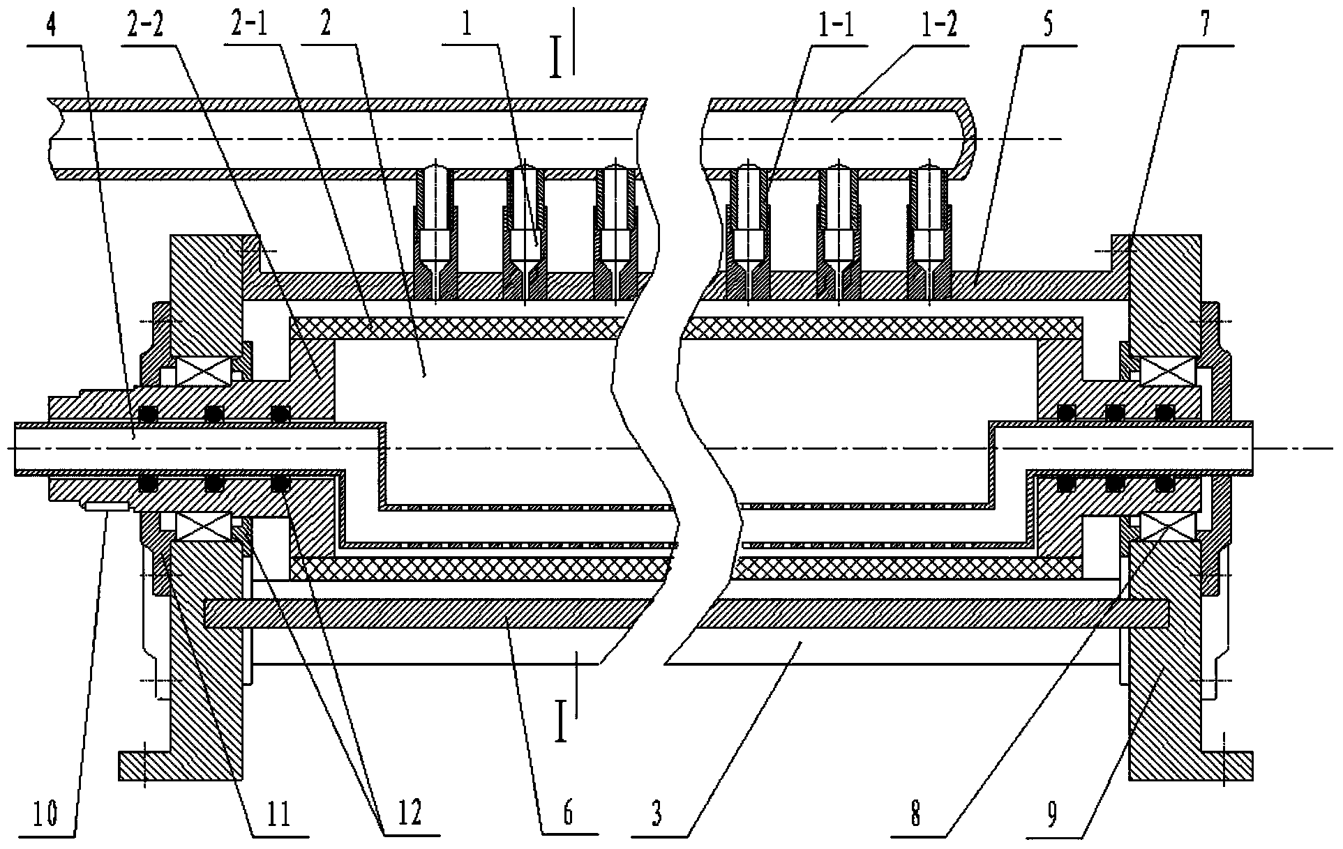
[0026] Embodiment one, the embodiment of supercritical fluid jet dyeing injector, as figure 1 , figure 2 , image 3 shown.

[0027] It consists of nozzle 1, nozzle branch pipe 1-1, nozzle main pipe 1-2, cloth dyeing roller 2, return pipe 4, cloth guide roller 3, fairing 5, baffle plate 14, overflow barrier 6 and side wall plate 9.

[0028] The cloth dyeing roller 2 is made up of a porous cylinder 2-1 and a hollow journal 2-2. The hollow journal 2-2 is coaxially installed at both ends of the porous cylinder 2-1, and the inner hole of the hollow journal 2-2 Return pipe 4 is installed, and the endoporus of hollow journal 2-2 is sealed with seal 12 with backflow pipe 4 matching positions; The hollow journal 2-2 of cloth dyeing roller 2 two ends is installed on the side wall plate 9 by bearing 8, and Install the transmission gear or sprocket on the hollow journal 2-2 at one end through the key or spline 10; install the cloth guide roller 3 at the position parallel to the axis o...

Embodiment 2

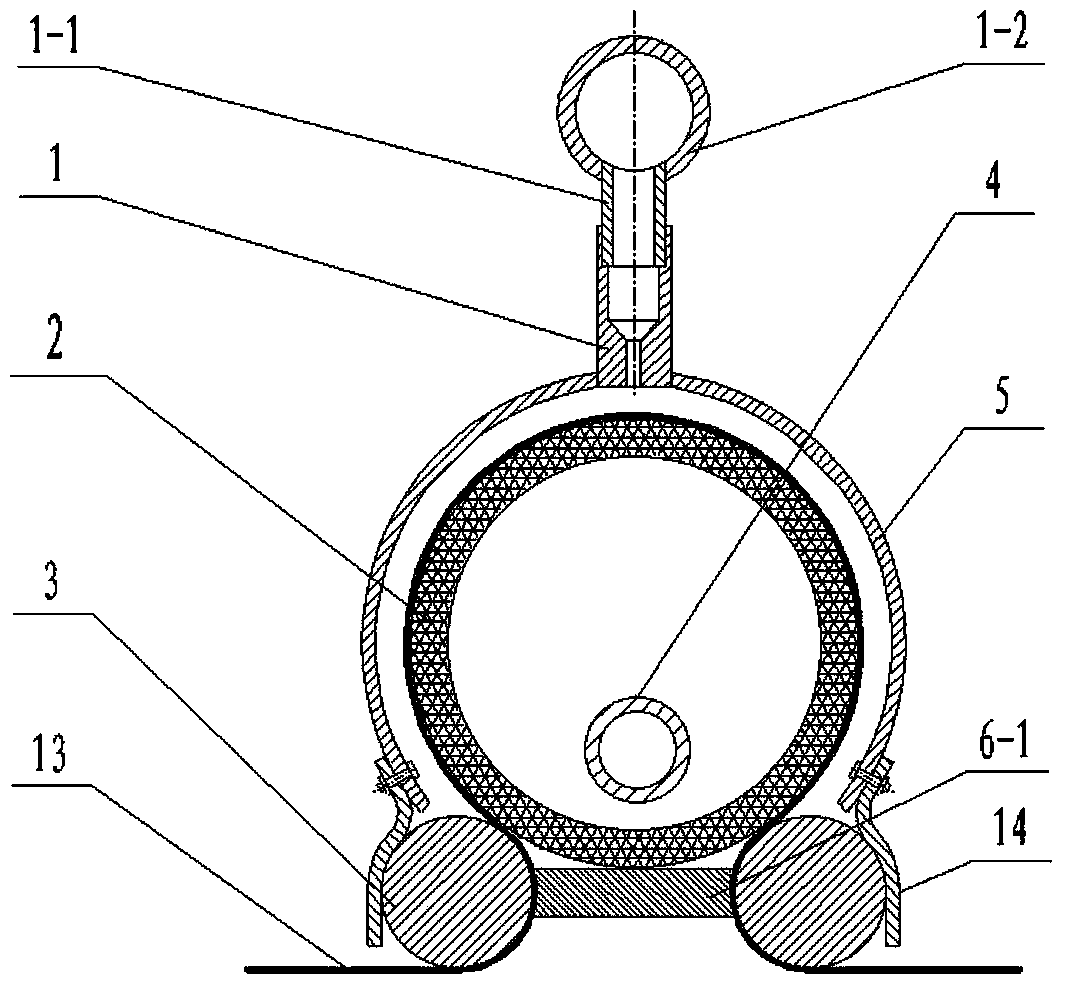
[0030] Embodiment two, the implementation process of the supercritical fluid dyeing injector device of single-side spraying, such as Figure 5 and Figure 8 shown.

[0031] Each injector is distributed along the same side of the object to be dyed 13, and along the direction in which the object to be dyed 13 travels, the cleaning injector 20, the dyeing injector 21 and the rinsing injector 22 are arranged successively, wherein the number of dyeing injectors 22 can be determined according to the specific dyeing process. One or more are required; each injector is installed on the frame 16 through the foundation of the bolt 7 and the side wall plate 9, and the tension wheel 15 is installed through the frame 16 between each injector.

[0032] Along the direction of travel of the dyed object 13, the nozzles 1 of the first injector are collected from the nozzle branch pipe 1-1 to the nozzle main pipe 1-2 and then connected to the supercritical fluid generation subsystem 18, and the ...

Embodiment 3

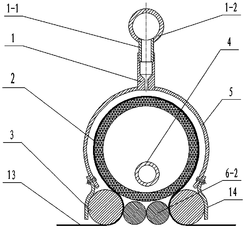
[0040] Embodiment three, the supercritical fluid spraying device of double-sided spraying, as Figure 6 , Figure 7 and Figure 8 shown.

[0041] In this embodiment, the structure of the single injector is the same as that of the first embodiment, and the way of connecting the single injector to other subsystems is the same as that of the second embodiment.

[0042] One or more injectors form a group, which are alternately distributed on both sides of the dyed object 13, and along the direction of the dyed object, the first group is cleaning injectors 20, the last group is rinsing injectors 22, and the middle groups are dyeing injectors. Injector 21, the quantity of dyeing injector 22 can be one or more groups according to specific dyeing process requirements; Each injector is installed on the frame 16 by the foundation of bolt 7 and side wall plate 9, and adjacent A tension wheel 15 is installed through a frame 16 between the outlet and inlet positions of the dyed matter o...


PUM


Abstract

The invention relates to the field of textile dyeing equipment, in particular to an ejector for supercritical fluid jet dyeing. The ejector is composed of a jet nozzle, jet nozzle branch pipes, a jet nozzle header pipe, a dyeing roller, a backflow pipe, a cloth guide roller, a flow rectification cover, a flow baffle, an overflow fence and a side wall plate. If the jet nozzle header pipe is connected with a supercritical fluid generation subsystem pipeline and the two ends of the backflow pipe are connected with a used-fluid recovery and separation subsystem pipeline, a cleaning ejector or rinsing ejector can be formed. If the jet nozzle header pipe is connected with a dye dissolution subsystem pipeline and the two ends of the backflow pipe are connected with the used-fluid recovery and separation subsystem pipeline, a dyeing ejector can be formed and operates under single-machine drive or group drive. The ejector solves the problems that under the action of a high-pressure jet and traction force, textiles to be dyed are deformed and damaged under tensile force and the pressure drop of the supercritical fluid jet is too large. Various supercritical fluid jet dyeing devices can be formed by combining a plurality of ejectors in different modes according to dyeing process requirements. The ejector is simple and compact in structure and good in manufacturability.

Description

1. Technical field [0001] The invention relates to the field of textile dyeing equipment, in particular to an injector for supercritical fluid spraying and dyeing. 2. Technical background [0002] The processing technology of traditional dyeing equipment has problems such as high water consumption, high energy consumption, long process, difficult sewage treatment and high cost. Supercritical fluid dyeing, especially supercritical carbon dioxide dyeing, uses supercritical fluid instead of water as the carrier of the dye to achieve water-free dyeing, thus fundamentally solving the problem of water pollution in the dyeing industry. At the same time, supercritical fluid dyeing technology has the advantages of supercritical fluid recycling, no pollution discharge, no drying of dyed objects, less fiber damage, simple and quick operation, high dyeing efficiency and low energy consumption, and has a good development and application prospect. [0003] At present, most supercritical ...

Claims


Application Information

Patent Timeline
IPC IPC(8): D06B9/02D06B23/20
Inventor 王威强王明禄曲延鹏刘燕王贺
Owner SHANDONG UNIV
Why Eureka
Try Eureka