High-speed precise double servo feed drilling power head

A technology of precision drilling and dual servos, which is applied in the direction of driving device, boring/drilling, drilling/drilling equipment, etc., which can solve the problem of inability to ensure the straightness and rigidity of the spline shaft, the inability to meet the miniaturization of equipment, and the inability to adjust accumulation Error and other problems, to achieve good automation control effect, meet the miniaturization of equipment, and improve production efficiency

Inactive Publication Date: 2014-06-25
SUGINO CHANGSHU CO LTD
View PDF6 Cites 7 Cited by
  • Summary
  • Abstract
  • Description
  • Claims
  • Application Information

AI Technical Summary

Problems solved by technology

However, its structure cannot meet the processing requirements of small-diameter holes. The reasons are as follows: First, the rotating power provided for drilling is an asynchronous motor, so the controllability of the motor is poor. Different ratios can only be achieved by changing the ratio of the pulleys. Spline shaft rotation speed; Secondly, the transmission structure of the servo motor in the servo feed control mechanism is also decelerated by a pair of synchronous pulleys according to a certain speed ratio. There are many parts and the structure is not compact, which cannot meet the requirements of equipment miniaturization. Moreover, the mechanical error increases due to excessive mechanical transmission; thirdly, the guidance of the sliding block is realized by only one guide post, and the cumulative error caused by assembly cannot be adjusted, so that it is impossible to ensure that the spline shaft has good straightness and better rigidity

Method used


Image

  • High-speed precise double servo feed drilling power head

Examples


Embodiment Construction

[0017] In order to enable the examiners of the patent office, especially the public, to more clearly understand the technical essence and beneficial effects of the present invention, the applicant will describe in detail below by way of examples, but the descriptions of the examples are not intended to describe the solution of the present invention. Restriction, any equivalent transformation made according to the concept of the present invention is only formal but not substantive, and should be regarded as the scope of the technical solution of the present invention.

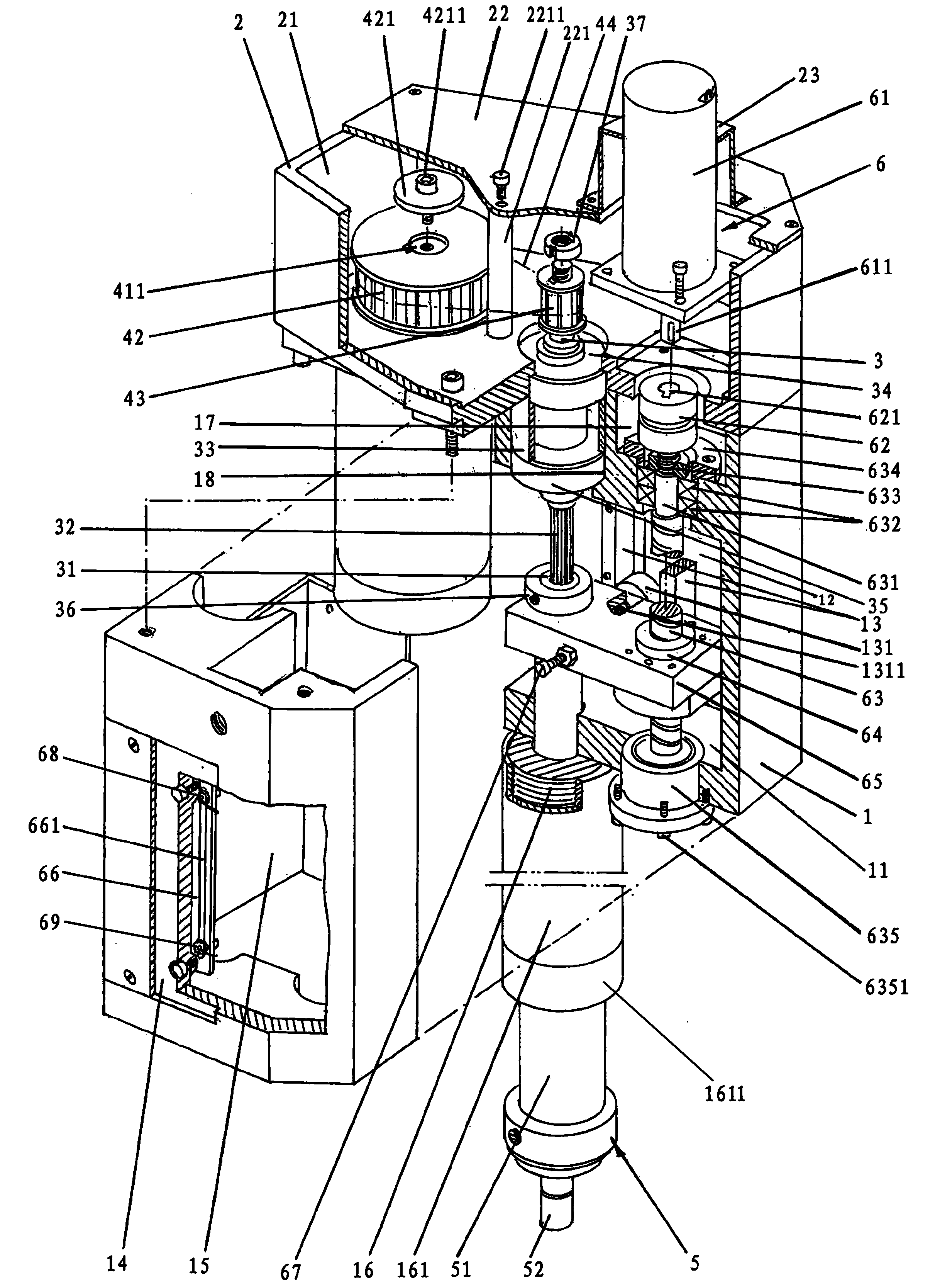
[0018] See figure 1 , a transmission box fixing seat 1 is given. Taking the current position shown as an example (the same below), the upper part of the transmission box fixing seat 1 is formed with a coupling cavity 17 and a bearing cavity 18, and the lower part is formed with a fixed The seat bottom plate 11 , the right side is formed with the fixed seat right wall plate 12 , the left side is formed with the f...


PUM


Abstract

The invention provides a high-speed precise double servo feed drilling power head, and belongs to the technical field of drilling tools. The power head comprises a transmission case fixing base, a transmission case, a spline shaft, a spline shaft driving mechanism, a workpiece drilling mechanism and a servo feed control mechanism, and is characterized in that the spline shaft driving mechanism comprises a first servo motor, a large synchronous pulley, a small synchronous pulley and a transmission belt; the servo feed control mechanism comprises a second servo motor, a coupler, a ball screw, a lead screw nut, a sliding block, a stroke contactor, a driver adjustment plate, a first stroke limiting sensor and a second stroke limiting sensor; guide rails are arranged on wallboards of the transmission case fixing base, and an idler wheel is installed on the side face of the sliding block and is located between the two guide rails. Under the circumstance that no mechanical part is replaced, the rotating speed of a main shaft can be adjusted at will so that the requirement that different hole diameters correspond to different cutting speeds can be met; efficiency is high, the size is small, and the requirements for high-speed and high-precision machining of small hole diameters can be met; it is guaranteed that the main shaft has good straightness and good rigidity; the automated control effect is good.

Description

technical field [0001] The invention belongs to the technical field of drilling tools, and in particular relates to a dual-servo feed high-speed precision drilling power head, especially capable of machining small-diameter holes on metal workpieces with high speed and high precision. Background technique [0002] At present, the common pneumatic drilling power heads and servo feeding drilling power heads on the market, on the one hand, the rotation of the main shaft (also known as the spline shaft) is driven by an asynchronous motor. Due to the poor controllability of this motor, As a result, the power head can only achieve the purpose of adjusting the rotation speed of the main shaft by changing the ratio of the pulley connected to the motor and the pulley connected to the main shaft. For users who frequently change the machining aperture and need to frequently change the spindle speed, the continuous replacement of the pulley not only reduces the production efficiency, bu...

Claims


Application Information

Patent Timeline
Patent Type & Authority Applications(China)
IPC IPC(8): B23B47/06B23B39/10
CPCB23B39/10B23Q5/10
Inventor 徐冠平赵苗龚喜徐斌戴义明殷冬敏
Owner SUGINO CHANGSHU CO LTD
Why Eureka
Try Eureka