Gas-liquid contact type residual heat recovery device

A waste heat recovery, gas-liquid contact technology, applied in direct contact heat exchangers, heat exchanger types, water shower coolers, etc. Unfavorable recycling and utilization problems, to achieve the effect of light weight, simple structure, and sufficient mass transfer

Active Publication Date: 2014-06-25
GUANGXI DETIAN CHEM CYCLE CO LTD
View PDF6 Cites 2 Cited by
  • Summary
  • Abstract
  • Description
  • Claims
  • Application Information

AI Technical Summary

Problems solved by technology

[0003] At present, waste heat recovery from flue gas and low-pressure steam (spent) steam will encounter two problems: one is the use of tube-and-tube heat exchangers, steam (gas) goes outside the pipe, and water goes inside the pipe. Due to the low heat transfer coefficient, equipment investment The second is to adopt partition wall heat transfer. Due to the low heat transfer coefficient of the flue gas side, in order to prevent equipment corrosion, the outlet flue temperature should not be too low, and should be slightly higher than the flue gas dew point corrosion temperature. Therefore, small and medium-sized boilers, kilns The exhaust gas temperature of the furnace should be controlled at about 180°C, for this reason, the effect of flue gas waste heat recovery is not significant
Since the waste heat of flue gas and low-pressure steam (spent) cannot be recovered and utilized to the greatest extent, the emission of harmful gases such as carbon dioxide and sulfur dioxide in the flue gas cannot be reduced. At the same time, the equipment is expensive, which is not conducive to flue gas and low-pressure steam. Recovery and Utilization of Steam Waste Heat

Method used


Image

  • Gas-liquid contact type residual heat recovery device

Examples


Embodiment Construction

[0017] The present invention will be described in detail below in conjunction with the accompanying drawings.

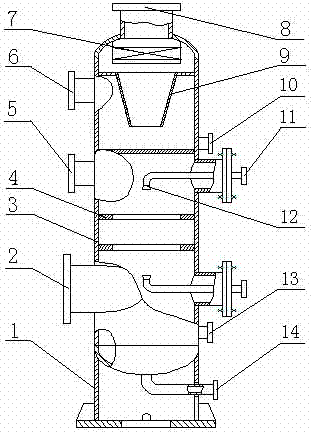
[0018] Such as figure 1 It can be seen from the schematic diagram of the front view of the structure of the present invention that the gas-liquid contact waste heat recovery device consists of a skirt 1, a gas inlet pipe 2, a shell 3, an annular liquid blocking plate 4, a gas screw-out tube 5, and a gas screw-in Pipe 6, demister 7, gas outlet pipe 8, gas distribution cone 9, liquid return outlet pipe 10, cold liquid inlet pipe 11, nozzle 12, liquid return inlet pipe 13, hot liquid outlet pipe 14, in which the shell 3 The lower part has a gas inlet pipe 2, which is connected to the gas input pipe; multiple nozzles 12 are installed in the housing 3, and the nozzles 12 are connected to the cold liquid inlet pipe 11, and connected to the cold liquid delivery pipe; The liquid plate 4 intercepts the liquid on the wall of the shell 3 and returns it to the gas rising space;...


PUM


Abstract

The invention discloses a gas-liquid contact type residual heat recovery device for recovering residual heat from flue gas and low-pressure steam. The residual heat recovery device is characterized in that a gas inlet pipe is arranged at the lower part of a shell and is connected with a gas input pipe; a plurality of spray heads are mounted in the shell and are connected with a cold liquid inlet pipe and a cold liquid conveying pipe; a plurality of annular liquid baffles are mounted in the shell; a liquid on the wall of the shell is intercepted and flows back to gas ascending space; a gas screw-out pipe is arranged at the upper part of the shell and is connected with a gas screw-in pipe; a gas distribution cone and a foam remover are mounted in the upper part of the shell, gas rotates at a high speed after entering a cyclone separator and then enters the foam remover through the gas distributor to separate the liquid from foam in gas flow; a liquid backflow outlet pipe is connected with a liquid backflow inlet pipe; a gas outlet pipe is connected with a gas emptying pipe; and a hot liquid outlet pipe is arranged at the lowest part of the shell and is connected with a hot liquid tank. The residual heat recovery device has the advantages of high heat exchange efficiency, capability of purifying flue gas, simple structure, reliability in working, convenience in mounting and the like.

Description

technical field [0001] The invention relates to a gas-liquid contact waste heat recovery device for waste heat recovery of flue gas and low-pressure steam (spent) steam. Background technique [0002] Small boilers and kilns that use gas, oil, and coal-water slurry as fuel will produce a large amount of flue gas, and processes that use steam as a heating medium or power will generate a large amount of low-pressure steam (exhausted) steam. These flue gases and Low-pressure steam (exhausted) steam contains a lot of heat. When it is discharged to the atmosphere, it will form a local "heat island effect". Waste and pollution of the environment. Due to their small power, the waste heat recovery of flue gas and low-pressure steam (exhausted) steam has not attracted enough attention, but they involve a wide range of areas and a large number. Research on how to recover and utilize flue gas and low-pressure steam (exhausted) steam The low-grade heat energy is an important topic of e...

Claims


Application Information

Patent Timeline
Patent Type & Authority Applications(China)
IPC IPC(8): F28C1/00B01D53/78
Inventor 钮德明
Owner GUANGXI DETIAN CHEM CYCLE CO LTD
Why Eureka
Try Eureka