
Synthetic aperture laser imaging radar bi-dimensional convolution imaging method

A synthetic aperture laser and imaging radar technology, which is applied to instruments, measurement devices, and re-radiation, etc., can solve the problems of inability to perform simultaneous operations, long processing time, and high requirements for computer performance, and achieves lower requirements and fewer imaging steps. Effect

Active Publication Date: 2014-06-25
SHANGHAI INST OF OPTICS & FINE MECHANICS CHINESE ACAD OF SCI
View PDF4 Cites 5 Cited by
  • Summary
  • Abstract
  • Description
  • Claims
  • Application Information

AI Technical Summary

Problems solved by technology

The above two steps are sequential in time and cannot be carried out at the same time. Therefore, the processing time of the SAIL target echo signal is longer. However, with the increase of synthetic aperture lidar detection targets, that is, the increase of target echo data , as well as the requirements for real-time imaging processing of the target, it will inevitably pose a severe challenge to the data processing system of the traditional synthetic aperture lidar imaging two-step focusing imaging processing
Prior Technology [Document 8: Sun Zhiwei, Zhi Yanan, Liu Liren, Hou Peipei, Sun Jianfeng, Zhou Yu, Synthetic Aperture Lidar Imaging Cross Focus Imaging Method, Invention Patent, Application No.: 201310017515.8; Document 9: Liu Liren, Synthetic Aperture Lidar Imaging Radar The two-dimensional Fourier transform imaging algorithm, Acta Optics Sinica, Vol.34(1):0128001(2014)] proposes that the SAIL echo signal is firstly compensated for the quadratic phase in the azimuth direction, and then two-dimensional fast Fourier transform is performed to obtain Imaging results, however, due to the large SAIL echo data matrix, the two-dimensional fast Fourier transform has high requirements for computer performance. In addition, the frequency domain imaging results obtained by the two-dimensional Fourier transform require two-dimensional frequency domain -The airspace coordinate conversion can be converted into actual airspace coordinates and display the imaging results, the process is more complicated

Method used


Image

  • Synthetic aperture laser imaging radar bi-dimensional convolution imaging method
  • Synthetic aperture laser imaging radar bi-dimensional convolution imaging method
  • Synthetic aperture laser imaging radar bi-dimensional convolution imaging method

Examples


Embodiment Construction

[0022] The present invention will be described in further detail below in conjunction with the accompanying drawings and embodiments, but the protection scope of the present invention should not be limited thereby.

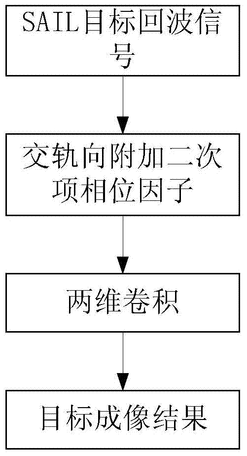
[0023] see first figure 1 , figure 1It is a schematic diagram of the steps of the synthetic aperture laser imaging radar cross-focus imaging method of the present invention. As can be seen from the figure, the synthetic aperture laser imaging radar cross-focus imaging method of the present invention, the steps include:

[0024] ①Synthetic aperture imaging lidar transmitting system irradiates laser light waves to the target, which is reflected by the target after being irradiated, and the reflected light wave is stored in the computer after photoelectric reception, digitization and complex processing by the synthetic aperture imaging lidar receiving system.

[0025] Side-view SAIL emits chirped pulsed laser with linear frequency modulation to the target, and the ...


PUM


Abstract

The invention provides a synthetic aperture laser imaging radar bi-dimensional convolution imaging method. The imaging method is characterized in that quadratic term phase factors are added to pluralized synthetic aperture laser imaging radar target echo signals in the cross rail direction, then focus imaging of the cross rail direction and the clockwise rail direction is achieved while bi-dimensional convolution is carried out, and the imaging result intensity signals are output and displayed. As convolution is adopted for carrying out focus imaging of the cross rail direction and the clockwise rail direction, the requirement for the performance of a computer from the imaging process can be lowered. In addition, space domain imaging results are directly obtained through bi-dimensional convolution, bi-dimensional frequency domain and space domain conversion is not needed, outputting and displaying are carried out directly, imaging procedures are reduced, and the imaging method is the important technology improvement of the synthetic aperture laser imaging radar echo signal imaging process.

Description

technical field [0001] The invention relates to a synthetic aperture laser imaging radar, in particular to a synthetic aperture laser imaging radar two-dimensional convolution imaging method for performing imaging processing on target echo signals received by a synthetic aperture laser imaging radar receiving system. Background technique [0002] The principle of Synthetic Aperture Lidar Imaging Lidar (SAIL) is derived from the principle of Synthetic Aperture Radar (SAR) in the microwave band. It is the only optical imaging observation method reported abroad that can obtain centimeter-level resolution at long distances. The traditional side-looking SAIL uses optical frequency linear modulation, that is, chirp modulation, to transmit laser light, and uses the same chirp laser light as the heterodyne local oscillator beam for photoelectric heterodyne reception. An echo difference frequency signal that contains distance information and phase history information in the azimuth d...

Claims


Application Information

Patent Timeline
IPC IPC(8): G01S17/89G01S7/48
CPCG01S7/4802G01S17/90
Inventor 孙志伟职亚楠孙建锋周煜侯培培刘立人
Owner SHANGHAI INST OF OPTICS & FINE MECHANICS CHINESE ACAD OF SCI
Learn More