A zinc-nickel flow battery structure and a zinc-nickel flow battery system
A technology for flow batteries and batteries, applied in fuel cells, fuel cell additives, regenerative fuel cells, etc., can solve the problems of complex structure and low battery operating current density, and achieve the goal of increasing operating current density, improving material transfer, simplifying Effects of battery system structure
- Summary
- Abstract
- Description
- Claims
- Application Information
AI Technical Summary
Problems solved by technology
Method used
Image
Examples
Embodiment 1
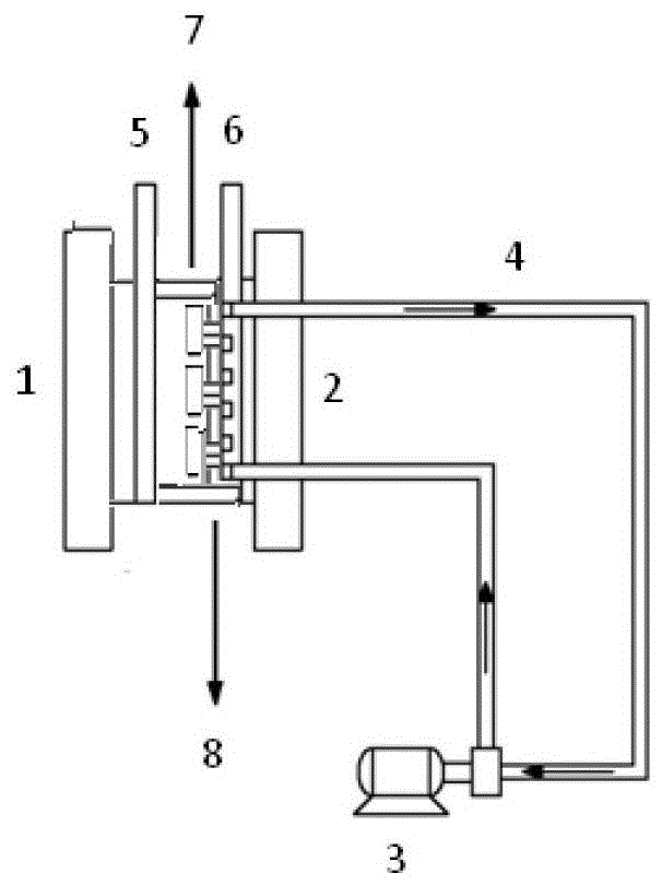
[0022] The battery structure and system consist of figure 1 As shown, it is composed of negative terminal plate, negative electrode, positive electrode flow field plate, positive electrode, positive electrode current collector, and positive terminal plate in turn; the battery system is composed of batteries, circulation pumps and pipelines, and the electrolyte is filled in the flow channels in the battery. The inlet and outlet of the electrolyte are connected through a pipeline through a circulation pump. When the battery is charged and discharged, the electrolyte is self-circulated inside the single cell or battery module through the pipeline under the action of the circulation pump.
[0023] The effective area of the positive and negative electrodes is 10*10cm; the material of the positive electrode current collector is graphite, and the positive electrode collector of the battery is equipped with a serpentine flow field with a flow channel depth of 0.4cm; the material of t...
Embodiment 2
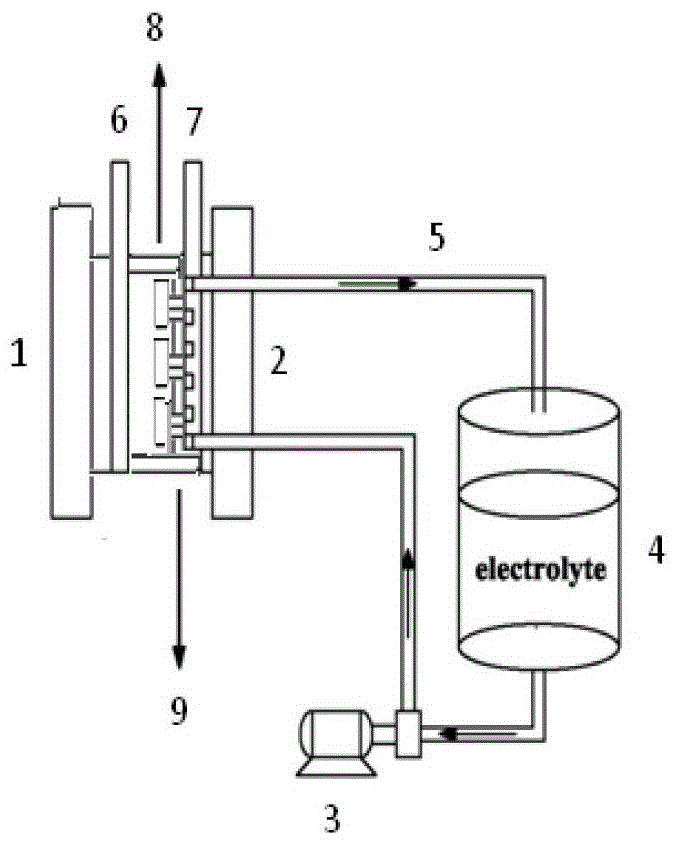
[0025] The battery structure and system consist of figure 2 As shown, the battery is composed of negative terminal plate, negative electrode, positive electrode flow field plate, positive electrode, positive electrode current collector, and positive terminal plate in sequence; the battery system is composed of battery, liquid storage tank, circulation pump and pipeline, and the liquid storage tank is filled with Electrolyte, the liquid storage tank is connected to the electrolyte inlet and outlet of the battery through pipelines, and a circulation pump is installed on the liquid storage tank and the electrolyte inlet or outlet pipeline of the battery; when the battery is charged and discharged, the electrolyte is circulated through the circulation pump Circulation between single cells or battery modules and liquid storage tanks.
[0026] The effective area of the positive and negative electrodes is 10*10cm; the material of the positive electrode collector is graphite, and t...
Embodiment 3
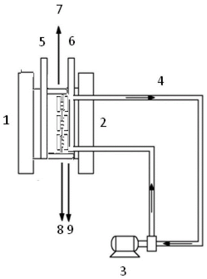
[0028] The battery structure and system consist of image 3 As shown, the battery is composed of negative terminal plate, negative electrode, positive flow field plate 1, positive electrode, positive flow field plate 2, positive current collector, and positive terminal plate; In the flow channel in the battery, the electrolyte inlet and outlet of the battery are connected through a pipeline through a circulation pump. When the battery is charged and discharged, the electrolyte is self-circulated inside the single cell or battery module through the pipeline under the action of the circulation pump.
[0029] The effective area of the positive and negative electrodes is 10*10cm; the material of the positive electrode current collector is graphite, and the positive electrode collector of the battery is equipped with a serpentine flow field with a depth of 0.8cm; the material of the positive electrode flow field plate is PC, the thickness is 0.3cm, and the flow path is serpentine ...
PUM
 Abstract
Description
Claims
Application Information
 - R&D
- Intellectual Property
- Life Sciences
- Materials
- Tech Scout
- Unparalleled Data Quality
- Higher Quality Content
- 60% Fewer Hallucinations
Browse by: Latest US Patents, China's latest patents, Technical Efficacy Thesaurus, Application Domain, Technology Topic, Popular Technical Reports.
© 2025 PatSnap. All rights reserved.Legal|Privacy policy|Modern Slavery Act Transparency Statement|Sitemap|About US| Contact US: help@patsnap.com


