Compensation voltage algorithm of inverter dead zone in motor control system and interpolation method

A technology for compensating voltage and motor control, which is applied in the control system, vector control system, motor generator control, etc. It can solve the problem of increasing the harmonic content of the output current of the inverter, increasing the flux distortion of the motor and torque ripple, and inverter It is impossible to fully compensate for the dead zone effect of the device, etc.

Active Publication Date: 2014-06-25
SHANGHAI DAJUN TECH
View PDF4 Cites 24 Cited by
  • Summary
  • Abstract
  • Description
  • Claims
  • Application Information

AI Technical Summary

Problems solved by technology

[0002] When the motor is running at low speed, especially at light load, the phase current and phase voltage are distorted due to the dead zone effect of the inverter and zero current clamping phenomenon occurs, which increases the current harmonic content of the inverter output; this current harmonic The content increases the flux linkage distortion and torque ripple of the motor
In the current motor control system, before the space vector pulse width modulation (SVPWM) control, how does the inverter get the accurate three-phase voltage U A , U B , U C In order to avoid the dead zone effect of the inverter, there are mainly the following methods: simply use the PID adjustment control to directly adjust the i d i q Perform pi adjustment to get u d , u q , and then through inverse park transformation and inverse clark transformation to get U A , U B ,

Method used


Image

  • Compensation voltage algorithm of inverter dead zone in motor control system and interpolation method
  • Compensation voltage algorithm of inverter dead zone in motor control system and interpolation method
  • Compensation voltage algorithm of inverter dead zone in motor control system and interpolation method

Examples


Embodiment Construction

[0039] The compensation voltage algorithm of the inverter dead zone in the motor control system of the present invention comprises the following steps:

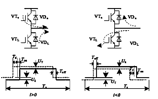
[0040] Step 1. Considering the inverter dead zone delay time T d , Inverter power tube turn-on time T on , off time T off 1. Under the influence of the conduction voltage drop of the power tube and the conduction voltage drop of the diode, taking the U phase of the inverter as an example, in a PWM cycle, calculate the error of the dead zone effect of the inverter according to the fact that the ideal and actual volt-second areas are equal time T err for:

[0041] T err =(T d +T on -T off +T ave )*sgn(i U ) (1)

[0042] in T ave = T on U d + ...


PUM


Abstract

The invention discloses a compensation voltage algorithm of an inverter dead zone in a motor control system and an interpolation method. The compensation voltage algorithm calculates the inverter dead zone effect error time Terr, equivalent error time Tave caused by conduction and voltage reduction of a power transistor and a diode in one PWM cycle is included, U-phase output end voltage error Vao_err caused by the Tave equivalent error time in one PWM cycle is calculated, three-phase voltage error of the inverter is thus obtained, and the compensation voltage of the inverter dead zone is obtained by the phase voltage error. According to the interpolation method, through sampling three-phase current of the inverter and carrying out filter processing by a current sensor, clark conversion, park conversion, inverted park conversion and inverted clark conversion are respectively carried out on the three-phase current after filter, three-phase current signals after filter are obtained, a zero-crossing threshold is set, and inverter compensation voltage interpolation can be carried out when the absolute value of the three-phase current is more than the threshold. With the algorithm, the compensation voltage can be obtained, and by adopting the interpolation method, the inverter dead zone effect can be avoided.

Description

technical field [0001] The invention relates to a compensation voltage algorithm and an interpolation method for an inverter dead zone in a motor control system. Background technique [0002] When the motor is running at low speed, especially at light load, the phase current and phase voltage are distorted due to the dead zone effect of the inverter and zero current clamping phenomenon occurs, which increases the current harmonic content of the inverter output; this current harmonic The content increases the flux linkage distortion and torque ripple of the motor. In the current motor control system, before the space vector pulse width modulation (SVPWM) control, how does the inverter get the accurate three-phase voltage U A , U B , U C In order to avoid the dead zone effect of the inverter, there are mainly the following methods: simply use the PID adjustment control to directly adjust the i d i q Perform pi adjustment to get u d , u q , and then through inverse park ...

Claims


Application Information

Patent Timeline
IPC IPC(8): H02M7/48H02M7/537H02P27/06H02P21/02
Inventor 赵洪涛张德徐性怡
Owner SHANGHAI DAJUN TECH
Why Eureka
Try Eureka