
Up-flow type coupling hydrolysis acidification pool

A hydrolytic acidification tank and flow-type technology, applied in anaerobic digestion treatment, etc., can solve the problems of high biomass, unmaintainable, poor mud-water separation efficiency, etc.

Active Publication Date: 2014-07-02
SHANGHAI HONESS ENVIRONMENTAL TECH CORP
View PDF8 Cites 4 Cited by
  • Summary
  • Abstract
  • Description
  • Claims
  • Application Information

AI Technical Summary

Problems solved by technology

Among them, the upflow sludge bed reactor distributes water through a water distribution device, and often adopts a gravity flow water distribution system or a pressure flow water distribution system. Both of these two water distribution systems have the problem that the water distribution orifice is easily blocked.
It is difficult to deal with after clogging, and if the treatment is not timely, it will lead to uneven water distribution, and long-term operation will produce dead zones, resulting in a decrease in the effective volume of the reaction pool
In addition, the separation system of the upflow sludge bed reactor usually adopts the elastic packing filling method, the separation efficiency of mud and water is poor, and it cannot maintain a high biomass
Although the hydrolytic acidification reactor with sludge return is equipped with an anaerobic hydrolysis device with sludge return, it needs to increase the sedimentation tank and sludge return pump, which not only increases the cost but also increases the operating cost.

Method used


Image

  • Up-flow type coupling hydrolysis acidification pool
  • Up-flow type coupling hydrolysis acidification pool
  • Up-flow type coupling hydrolysis acidification pool

Examples


Embodiment Construction

[0018] In order to make the technical means, creative features, goals and effects achieved by the present invention easy to understand, the present invention will be further described below in conjunction with specific diagrams.

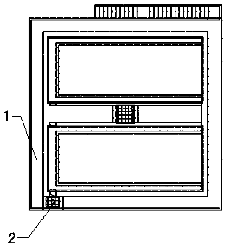
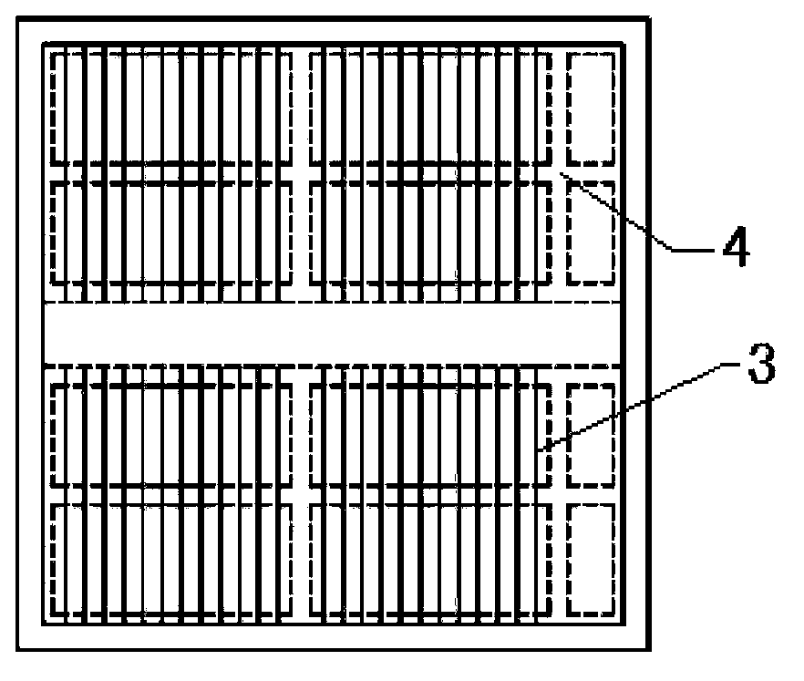
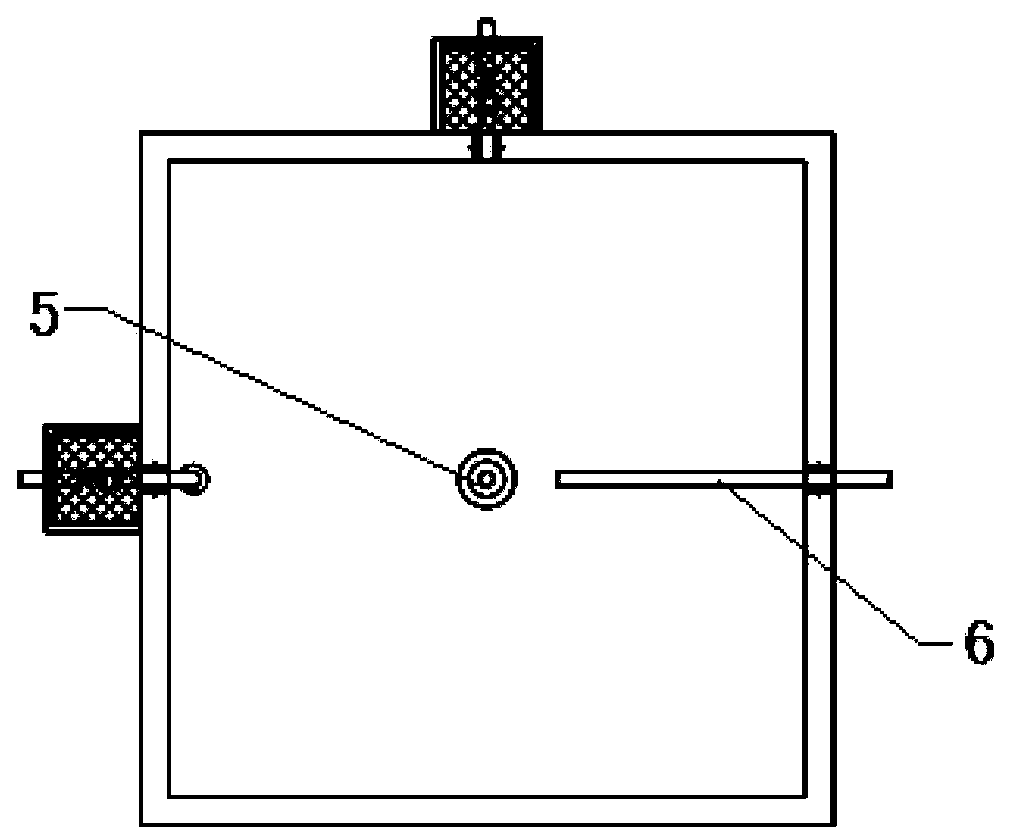
[0019] refer to figure 1 , figure 2 , image 3 and Figure 4 , an upflow coupled hydrolysis acidification tank, including a hydrolysis acidification tank, the hydrolysis acidification tank is followed by a clarification zone, a coupling precipitation reaction zone, and a sludge bed reaction zone from top to bottom, and a stirrer is arranged in the hydrolysis acidification tank, and the stirrer is Submersible mixer 5, the submersible mixer 5 is placed at the bottom of the hydrolysis acidification tank, located in the sludge bed reaction zone. Under the action of the submersible mixer 5, the sludge in the sludge bed reaction zone is quickly and evenly mixed. The sludge bed is similar to a filter layer, which quickly traps and absorbs the particulat...


PUM

PropertyMeasurementUnit
angleaaaaaaaaaa

Abstract

The invention relates to the technical field of sewage treatment. An up-flow type coupling hydrolysis acidification pool comprises a hydrolysis acidification pool body, wherein the hydrolysis acidification pool body sequentially comprises a clarifying region, a coupling settling reaction region and a sludge bed reaction region from top to bottom, a mixer is arranged in the hydrolysis acidification pool body and is a submersible mixer, and the submersible mixer is arranged at the bottom of the hydrolysis acidification pool body and is located in the sludge bed reaction region. Under the action of the submersible mixer, sludge in the sludge bed reaction region is rapidly and uniformly mixed, a sludge bed is similar to a filter layer, particular materials and colloidal materials, entering water, are rapidly intercepted and adsorbed and then decomposed by a large quantity of hydrolysis bacteria, many insoluble organic materials are hydrolyzed into soluble materials, and macromolecular and difficultly-biodegradable materials are converted into micromolecular and easily-biodegradable materials.

Description

technical field [0001] The invention relates to the technical field of sewage treatment, in particular to a hydrolytic acidification tank. Background technique [0002] Due to the poor biodegradability of industrial wastewater and municipal wastewater containing industrial wastewater, conventional treatment processes cannot meet the discharge requirements. Usually, a hydrolytic acidification process is added before the conventional treatment process to improve the biodegradability of wastewater, thereby improving the efficiency of the entire treatment system. The commonly used hydrolytic acidification reactors mainly include upflow sludge bed reactor and hydrolysis acidification reactor with sludge reflux. Among them, the upflow sludge bed reactor distributes water through a water distribution device, and often adopts a gravity flow water distribution system or a pressure flow water distribution system. Both of these two water distribution systems have the problem that the ...

Claims


Application Information

Patent Timeline
Patent Type & Authority Applications(China)
IPC IPC(8): C02F3/28
Inventor 王文标张凯王浩肖霄毛勇先
Owner SHANGHAI HONESS ENVIRONMENTAL TECH CORP
Learn More