Graphitization furnace surplus energy utilization method based on forced cooling

A graphitization furnace and forced cooling technology, applied in furnace cooling devices, chemical instruments and methods, furnaces, etc., can solve the problems of poor quality and variety of processed products, reduce heat loss, slow cooling speed, etc., and achieve important energy saving and emission reduction Benefits and economic and social benefits, reduce overall energy consumption, and speed up the production cycle

Inactive Publication Date: 2014-07-02
张茂勇
View PDF0 Cites 3 Cited by
  • Summary
  • Abstract
  • Description
  • Claims
  • Application Information

AI Technical Summary

Problems solved by technology

This old type of graphitization furnace is outdated, and it is a high-energy-consuming operation method
[0004] The structure of the traditional natural cooling graphitization furnace is as follows: figure 1 As shown, the cooling process of the graphitization furnace relies on the natural cooling between the outside of the outer wall and the ambient air, so the cooling speed is very slow, and the cooling time is more than 8 to 10 days, which greatly affects the production cycle and production capacity of the production line
[0005] Abroad, Japan has developed a new type of continuous operation graphitization furnace. The material to be processed moves slowly and heats up, which effectively reduces heat loss and saves electricity costs. The requirement above 2800°C makes the quality and variety of processed products inferior to static heating furnaces, so it has not been widely promoted in the industry
[0006] To sum up, there is currently no graphitization furnace production process in this field that can guarantee high-quality products, avoid consuming a lot of electricity and losing a lot of waste heat energy, and can generate electricity and heat through waste heat recovery.

Method used


Image

  • Graphitization furnace surplus energy utilization method based on forced cooling
  • Graphitization furnace surplus energy utilization method based on forced cooling

Examples


Embodiment Construction

[0014] The forced cooling-based graphitization furnace residual energy utilization method proposed by the present invention will be described in detail in combination with the accompanying drawings and embodiments.

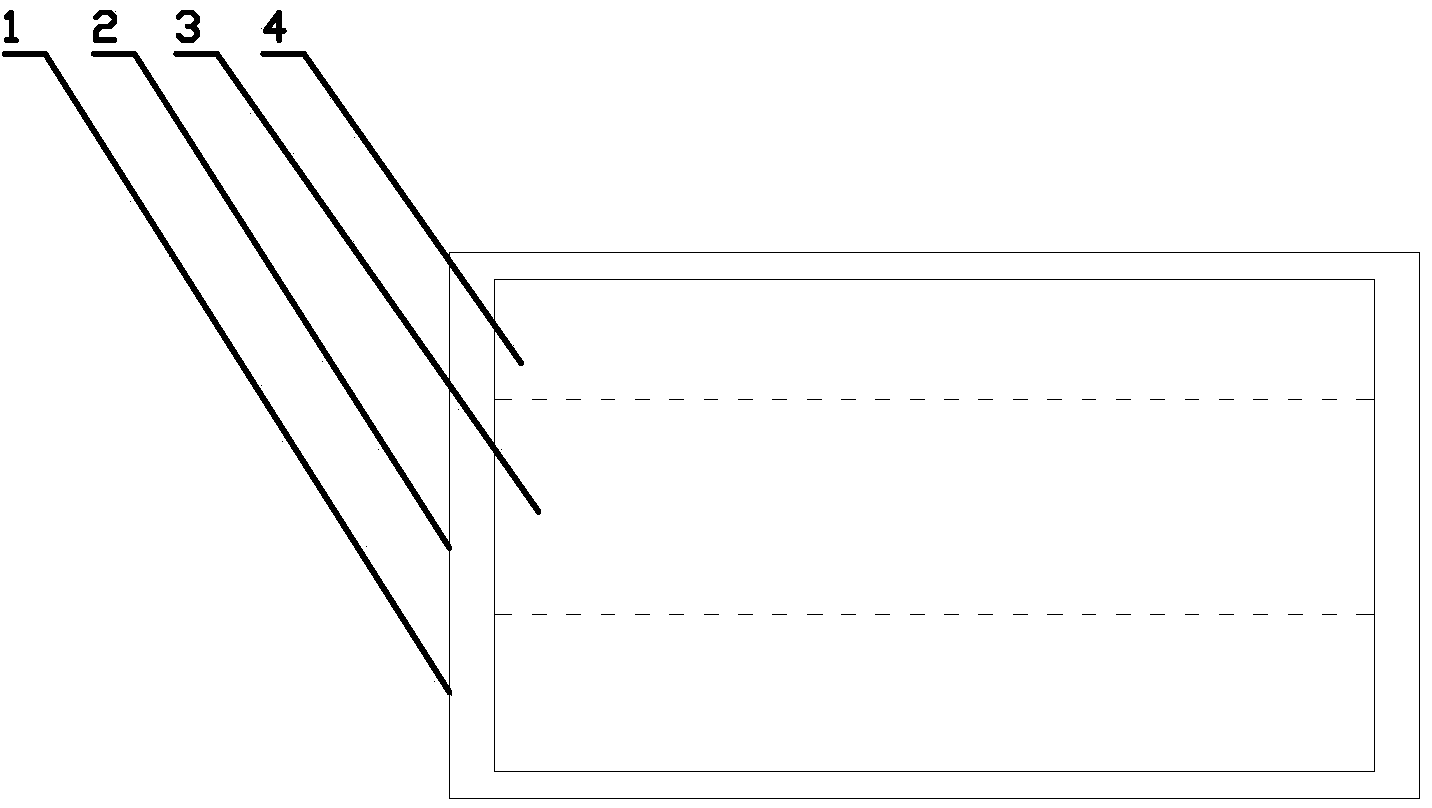
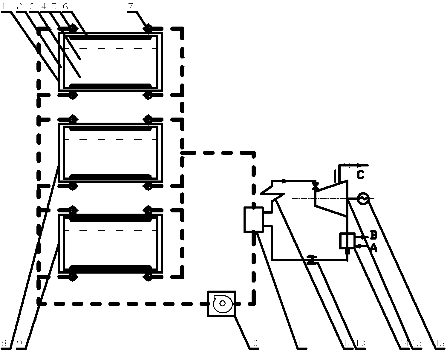
[0015] Specific embodiments of the present invention are as follows: a graphitization furnace residual energy utilization method based on forced cooling, wherein the graphitization furnace 1 is a cuboid furnace structure, and is respectively an outer wall 2, an insulation layer 3 and a furnace core 4 from outside to inside, A graphitization furnace production line includes multiple independent graphitization furnaces 1, No. 2 graphitization furnace 8, and N. The forced cooling device of the furnace, the waste heat boiler and the steam turbine generator set, the fan and the connecting pipeline are composed, and the forced cooling device is a group of cooling coils 6, which are embedded in the insulation layer 3 in the graphitization furnace, close to the outer wall ...


PUM


Abstract

The invention relates to a graphitization furnace surplus energy utilization method based on forced cooling. The cooling mode of a graphitization furnace is changed into forced cooling from natural cooling, waste heat obtained in the cooling process of a graphitization product is converted into steam through heat-carrying gas, electricity generation and heat supply are carried out, a cooling coil is arranged inside a furnace body, an air inlet of the cooling coil is connected with an air inlet collecting pipe, the air inlet collecting pipe is connected with a waste heat boiler through a cooling fan, an air outlet of the cooling coil is connected with an air outlet collecting pipe, the air outlet collecting pipe is connected with the waste heat boiler, and the steam enters a turbine system for electricity generation and heat supply. Each graphitization furnace production line comprises a plurality of independent furnace bodies, wherein in the cooling process, single furnace body is cooled intermittently, however, it is ensured that the furnace bodies of the whole production line are cooled at any time point, high-temperature gas always enters the waste heat boiler, and a turbine generator set can continuously work. According to the novel graphitization furnace cooling technology, the capacity of the graphitization product is remarkably improved, the comprehensive energy consumption is reduced, and the graphitization production technology is greatly improved.

Description

technical field [0001] The invention belongs to the fields of graphitization furnaces and industrial energy saving, and in particular relates to a forced cooling-based graphitization furnace residual energy utilization method. Background technique [0002] Graphitization furnaces are used to produce steelmaking carbon anode materials, battery negative electrode materials, carbon fibers, graphite heat-conducting materials, crucibles, carburizing agents, carbon composite materials and other special carbon material products. Usually, a kiln production line includes multiple identical furnace units , each furnace body of the existing old furnace type is divided into three layers horizontally from outside to inside: the clay brick outer wall is about 0.5m, the calcined coke insulation layer is about 0.8m, and the furnace core layer is the processed material layer and its filling material ( calcined petroleum coke). The operation process is as follows: Furnace loading—heating wit...

Claims


Application Information

Patent Timeline
Patent Type & Authority Applications(China)
IPC IPC(8): F27D17/00F27D1/12C01B31/04C01B32/205
CPCY02P10/25Y02P20/129
Inventor 张茂勇
Owner 张茂勇
Why Eureka
Try Eureka