Through-hole metal foam heat pipe heat exchange device with gradually-changed appearance characteristics
A metal foam and heat exchange device technology, applied in indirect heat exchangers, metal processing equipment, manufacturing tools, etc., can solve the problems of low heat exchange efficiency, large amount of consumables, and large volume of heat pipes, and achieve less metal consumables and increase in size. The effect of large heat transfer specific surface area and small volume
- Summary
- Abstract
- Description
- Claims
- Application Information
AI Technical Summary
Problems solved by technology
Method used
Image
Examples
preparation example Construction
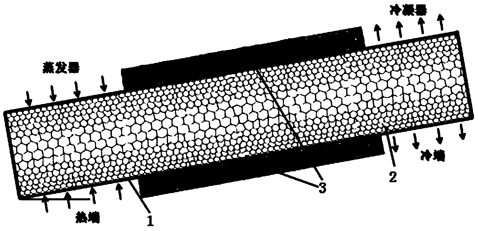
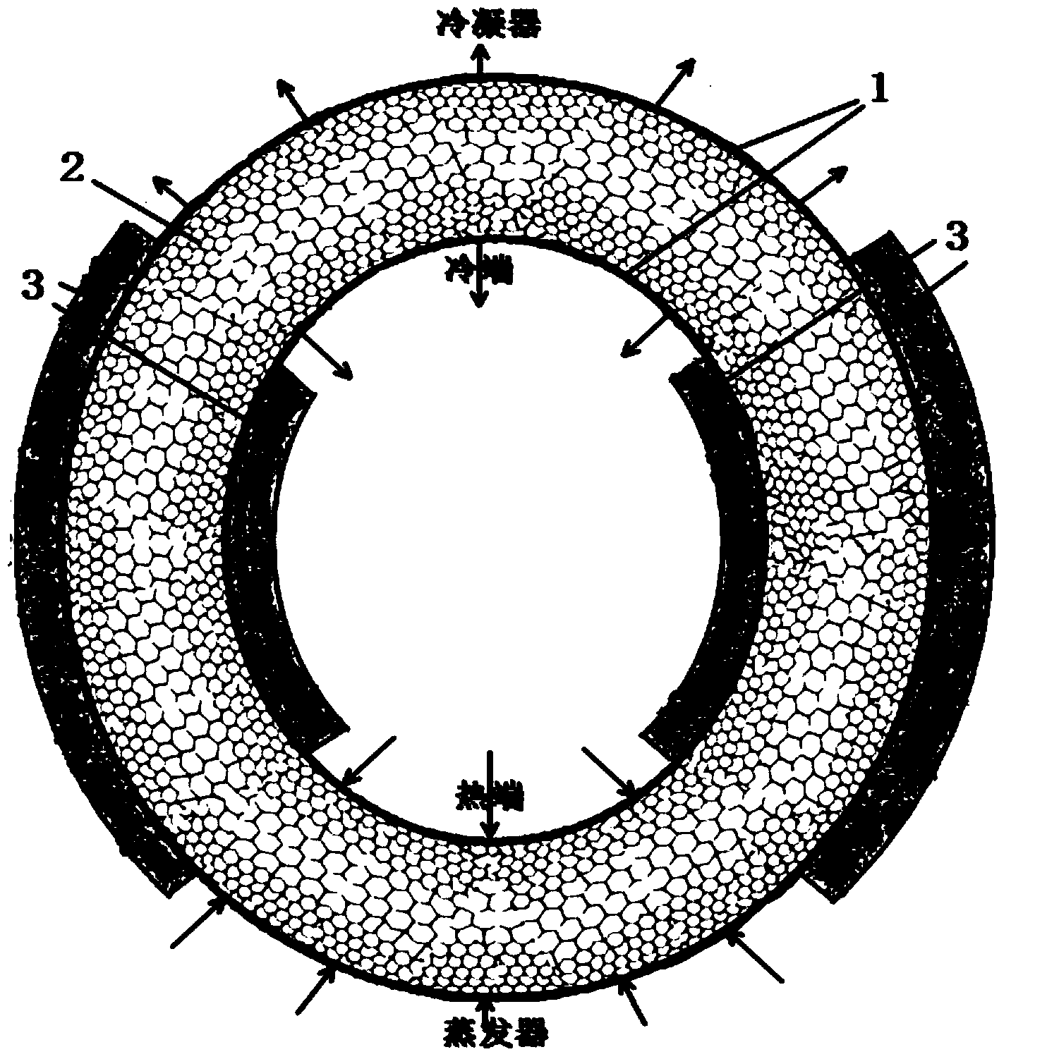
[0030] The preparation method of the through-hole metal foam 2 is by investment casting method, and its specific steps include:
[0031] The first step is to glue the polyurethane sponge with a pore density range of 3PPI-130PPI and a porosity range of 0.88-0.98 to form a whole; then immerse it in the liquid refractory material so that the refractory material fills its voids ;
[0032] The second step is to heat the polyurethane sponge after hardening to form a three-dimensional skeleton space that replicates the structure of the polyurethane sponge;
[0033] The third step is to pour the molten metal into the mold, and remove the refractory material after the metal is solidified to form a through-hole metal foam 2 with gradual deformation characteristics;
[0034] When preparing the graded metal foam whose material changes according to the layers, the metal foam prepared in the first step to the third step of each layer is welded together by brazing.
[0035] The refractory ...
Embodiment 1
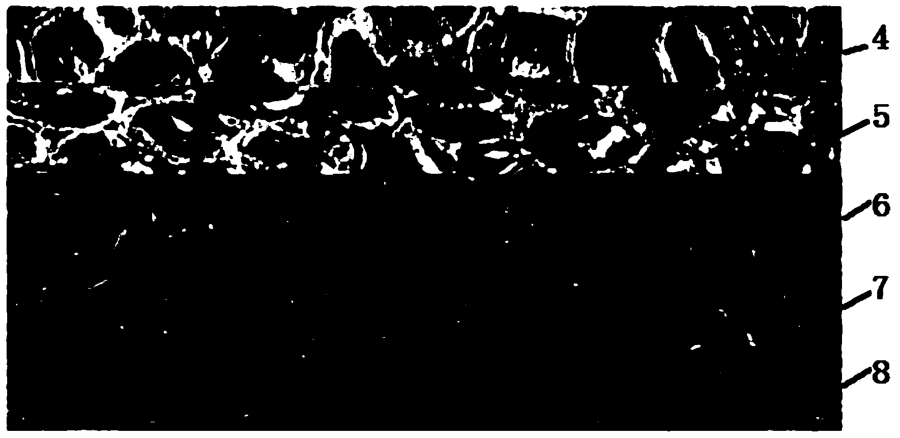
[0039] Such as figure 2 As shown, the through-hole metal foam 2 of the present embodiment is 5 layers of foam: the first through-hole copper foam layer 4, the second through-hole copper foam layer 5, the third through-hole copper foam layer 6, the fourth through-hole copper foam layer layer 7 and fifth via copper foam layer 8.
[0040] The density of 4 holes in the first through-hole copper foam layer is 40PPI; the density of 5 holes in the second through-hole copper foam layer is 30PPI; the density of 6 holes in the third through-hole copper foam layer is 20PPI; the density of 7 holes in the fourth through-hole copper foam layer is 10PPI; the 8-hole density of the fifth through-hole copper foam layer is 5PPI.
[0041] Specific steps of investment casting method:
[0042] The first step is to glue polyurethane sponges with pore densities of 40PPI, 30PPI, 20PPI, 10PPI and 5PPI layer by layer to form a whole; then immerse it in the liquid refractory material so that the refra...
Embodiment 2
[0047] The heat pipe 1 is arranged obliquely. The hole density of the through-hole metal foam 2 close to the heat pipe 1 can be selected as the highest hole density 130PPI, and the gradient of the hole density change vertically inward along the wall surface is relatively larger. The porosity is lower than 0.88, and the material is selected. Such as pure copper, brass, etc. In this way, at the hot end, the through-hole metal foam 2 close to the heat pipe 1 is dense, with many vaporization cores, and the gradient of density changes is large, which is more conducive to the rapid concentration of gas to the middle of the heat pipe 1 and rise to the cold end. ; At the cold end, more steam can be taken away by the outside world through the dense metal skeleton close to the heat pipe 1 wall, and the condensation efficiency is higher. If the heat transfer capacity of the heat pipe 1 is small, the inclination of the heat pipe 1 can also be reduced to reduce the effect of gravity on the...
PUM
| Property | Measurement | Unit |
|---|---|---|
| porosity | aaaaa | aaaaa |
Abstract
Description
Claims
Application Information
 - R&D
- Intellectual Property
- Life Sciences
- Materials
- Tech Scout
- Unparalleled Data Quality
- Higher Quality Content
- 60% Fewer Hallucinations
Browse by: Latest US Patents, China's latest patents, Technical Efficacy Thesaurus, Application Domain, Technology Topic, Popular Technical Reports.
© 2025 PatSnap. All rights reserved.Legal|Privacy policy|Modern Slavery Act Transparency Statement|Sitemap|About US| Contact US: help@patsnap.com


