Method and device for preventing thermal-power boiler from quick coking and ash deposition

A boiler and ash accumulation technology, which is applied in combustion methods, lighting and heating equipment, and removal of solid residues, etc., can solve the problem of inability to ensure sufficient contact between fuel and air for combustion, large disturbances in the flow field in the furnace, and inability to ensure complete coverage of the heating surface Surface and other problems, to achieve the effects of coking and dust deposition prevention, corrosion control, and inhibition of NOx formation

Inactive Publication Date: 2014-07-09
HUAZHONG UNIV OF SCI & TECH
View PDF5 Cites 10 Cited by
  • Summary
  • Abstract
  • Description
  • Claims
  • Application Information

AI Technical Summary

Problems solved by technology

[0006] However, unlike waste heat boilers, the radiant heating surfaces such as water-cooled walls of thermal power boilers are distributed on the furnace wall. Any air flow introduced from the outside must first ensure that it does not affect the combustion process in the furnace and the heat exchange efficiency of the boiler. If the air curtain mentioned in the plan is adopted In this way, the air flow of the air curtain greatly disturbs the flow field in the furnace, which cannot ensure the full contact combustion of fuel and air
In addition, the above solution has a certain distance between the air curtain and the heating surface, so there is a hidden danger of backflow of the air curtain airflow, and the airflow inlet adopts the nozzle type, which cannot guarantee complete coverage of the heating surface surface
Therefore, the above air curtain method has great limitations and is only suitable for boilers without combustion process such as tunnel waste heat boilers

Method used


Image

  • Method and device for preventing thermal-power boiler from quick coking and ash deposition

Examples


Embodiment Construction

[0031] In order to make the object, technical solution and advantages of the present invention clearer, the present invention will be further described in detail below in conjunction with the accompanying drawings and embodiments. It should be understood that the specific embodiments described here are only used to explain the present invention, not to limit the present invention. In addition, the technical features involved in the various embodiments of the present invention described below can be combined with each other as long as they do not constitute a conflict with each other.

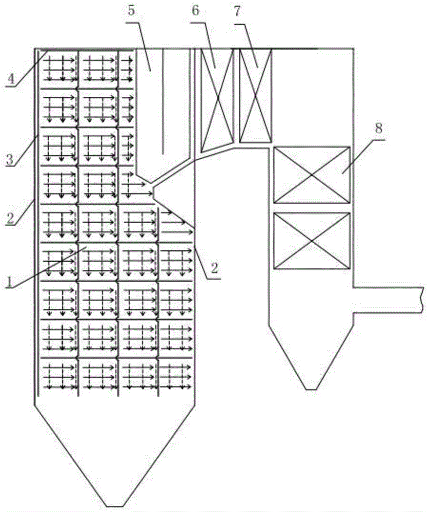
[0032] The single / double-layer gas film device for preventing rapid coking and ash accumulation of thermal power boilers in this embodiment, such as figure 1 As shown, taking a common Π-type coal-fired boiler as an example, water-cooled walls 2 are distributed on the walls around the boiler furnace 1. The high-temperature flue gas generated by fuel combustion in the furnace reaches the upper part ...


PUM


Abstract

The invention discloses a method for preventing a thermal-power boiler from quick coking and ash deposition. The method is characterized by including that flowing gas with certain momentum is blown in along a heated face of the boiler in a wall-adhering manner to flow on the heated face of the boiler in a wall-adhering manner to form a gas boundary layer adhered to the heated face, so that speed and composition of an original gas boundary layer are changed, molten mineral substances are avoided from contacting with the heated face, the molten mineral substances are enabled to be less prone to attaching on the heated face, and inhibition on coking and ash deposition of the heated face of the thermal-power boiler is realized; a gas protection layer can ba additionally arranged outside the gas boundary layer according to needs; gas flowing direction can be vertical, horizontal, obliquely downward or obliquely upward. The invention further discloses a boundary layer gas generating device for preventing the heated face of the boiler from coking and ash deposition. By the method and the device, the formed gas boundary layer can be ensured to play an effective role in protection, purified smoke containing a lot of CO2 can be led back into a hearth, NOx generation can be inhibited, heat exchange coefficient of the convective heated face can be increased, and corrosion of the heated face can be controlled.

Description

technical field [0001] The invention belongs to the technical field of boiler coking and ash deposition control, and specifically relates to a method and device for preventing coking and ash deposition on the heating surface of a boiler. The heating surface of boilers with heavy metal or highly volatile mineral fuels quickly cokes and accumulates dust. Background technique [0002] The current situation of my country's energy structure determines that thermal power generation is the main way of energy supply in our country. However, during the operation of thermal power boilers, the flue gas produced by combustion contains a large amount of sulfide, sulfur oxides, nitrogen oxides and alkali metal oxides, forming ash particles. When the earth is orbiting, the molten ash particles carried by it will condense on the radiation heating surface such as the water wall of the boiler to form coke; and on the convection heating surface such as the superheater and economizer, the accu...

Claims


Application Information

Patent Timeline
Patent Type & Authority Applications(China)
IPC IPC(8): F23J3/02
Inventor 傅培舫岳芳
Owner HUAZHONG UNIV OF SCI & TECH
Why Eureka
Try Eureka