Method for measuring electro-optic phase modulator modulation factor
An electro-optical phase modulation and modulation coefficient technology, applied in the field of optoelectronics, can solve the problems of separate calibration of photodetector frequency response, etc., to avoid the influence of photodetector response, improve stability, and realize the effect of self-calibration measurement
- Summary
- Abstract
- Description
- Claims
- Application Information
AI Technical Summary
Problems solved by technology
Method used
Image
Examples
Embodiment 1
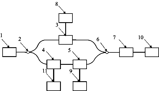
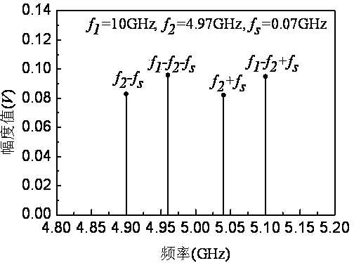
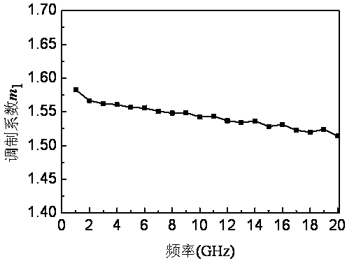
[0063] Set the output wavelength of laser 1 to λ 0 =1553.60nm (corresponding frequency f 0 =193.1THz), taking one of the measurement frequency points as an example, the frequency f of the sinusoidal signal output by the first signal source 8 1 =10GHz, the sinusoidal signal frequency f of the second microwave signal source 9 output 2 =4.97GHz, the sinusoidal signal frequency f of the third signal source 11 output s =0.07GHz, the frequency in the signal of the output signal of the optical fiber interferometer under the action of the above three sinusoidal signals by the sampling circuit 10 is 4.96GHz (f 1 -f 2 -f s ), 5.1GHz (f 1 -f 2 +f s ), 4.9GHz (f 2 -f s ), 5.04GHz (f 2 +f s ) magnitude, respectively denoted as i(f 1 -f 2 +f s ), i(f 1 -f 2 -f s ), i(f 2 +f s ), i(f 2 -f s ); figure 2 In this embodiment, the method for measuring the modulation coefficient of the electro-optical phase modulator of the present invention is used to obtain the amplitude v...
Embodiment 2
[0069] Set the output wavelength of laser 1 to λ 0 =1551.19nm (corresponding frequency f 0 =193.4THz), taking one of the measurement frequency points as an example, the frequency f of the sinusoidal signal output by the first signal source 8 1 =20GHz, the sinusoidal signal frequency f of the second microwave signal source 9 output 2 =9.9GHz, the sinusoidal signal frequency f of the third signal source 11 output s =0.08GHz, the frequency in the signal of the output signal of the optical fiber interferometer under the effect of the above three sinusoidal signals by sampling circuit 10 is 9.82GHz (f 2 -f s ), 9.98GHz (f 2 +f s ), 10.02GHz (f 1 -f 2 -f s ), 10.18GHz (f 1 -f 2 +f s ) magnitude, respectively denoted as i(f 2 -f s ), i(f 2 +f s ), i(f 1 -f 2 -f s ), i(f 1 -f 2 +f s ); Figure 4 In this embodiment, the method for measuring the modulation coefficient of the electro-optical phase modulator of the present invention is used to obtain the amplitude va...
Embodiment 3
[0075] Set the output wavelength of laser 1 to λ 0 =1550.55nm (corresponding frequency f 0 =193.48THz), taking one of the measurement frequency points as an example, set the frequency f of the sinusoidal signal output by the first signal source 8 1 =15GHz, the sinusoidal signal frequency f of the second microwave signal source 9 output 2 =7.46GHz, the sinusoidal signal frequency f of the third signal source 11 output s =0.1GHz, the frequency in the signal of the output signal of the optical fiber interferometer under the action of the above three kinds of sinusoidal signals by the sampling circuit 10 is 7.44GHz (f 1 -f 2 -f s ), 7.64GHz (f 1 -f 2 +f s ), 7.36GHz (f 2 -f s ), 7.56GHz (f 2 +f s ) magnitude, respectively denoted as i(f 1 -f 2 +f s ), i(f 1 -f 2 -f s ), i(f 2 +f s ), i(f 2 -f s ); Figure 6 In this embodiment, the method for measuring the modulation coefficient of the electro-optical phase modulator of the present invention is used to obtain ...
PUM
 Abstract
Description
Claims
Application Information
 - R&D
- Intellectual Property
- Life Sciences
- Materials
- Tech Scout
- Unparalleled Data Quality
- Higher Quality Content
- 60% Fewer Hallucinations
Browse by: Latest US Patents, China's latest patents, Technical Efficacy Thesaurus, Application Domain, Technology Topic, Popular Technical Reports.
© 2025 PatSnap. All rights reserved.Legal|Privacy policy|Modern Slavery Act Transparency Statement|Sitemap|About US| Contact US: help@patsnap.com


