High-power built-in permanent magnet synchronous motor position-sensorless control system and control method

A permanent magnet synchronous motor, built-in technology, applied in the direction of control system, vector control system, motor generator control, etc., can solve the problem of increasing low-order harmonic components

Inactive Publication Date: 2014-07-16
HARBIN INST OF TECH
View PDF4 Cites 24 Cited by
  • Summary
  • Abstract
  • Description
  • Claims
  • Application Information

AI Technical Summary

Problems solved by technology

[0005] The present invention aims to solve the problem that the low-order harmonic component increases when the traditional high-power built-in permanent magnet synchronous motor system wo

Method used


Image

  • High-power built-in permanent magnet synchronous motor position-sensorless control system and control method
  • High-power built-in permanent magnet synchronous motor position-sensorless control system and control method
  • High-power built-in permanent magnet synchronous motor position-sensorless control system and control method

Examples


specific Embodiment approach 1

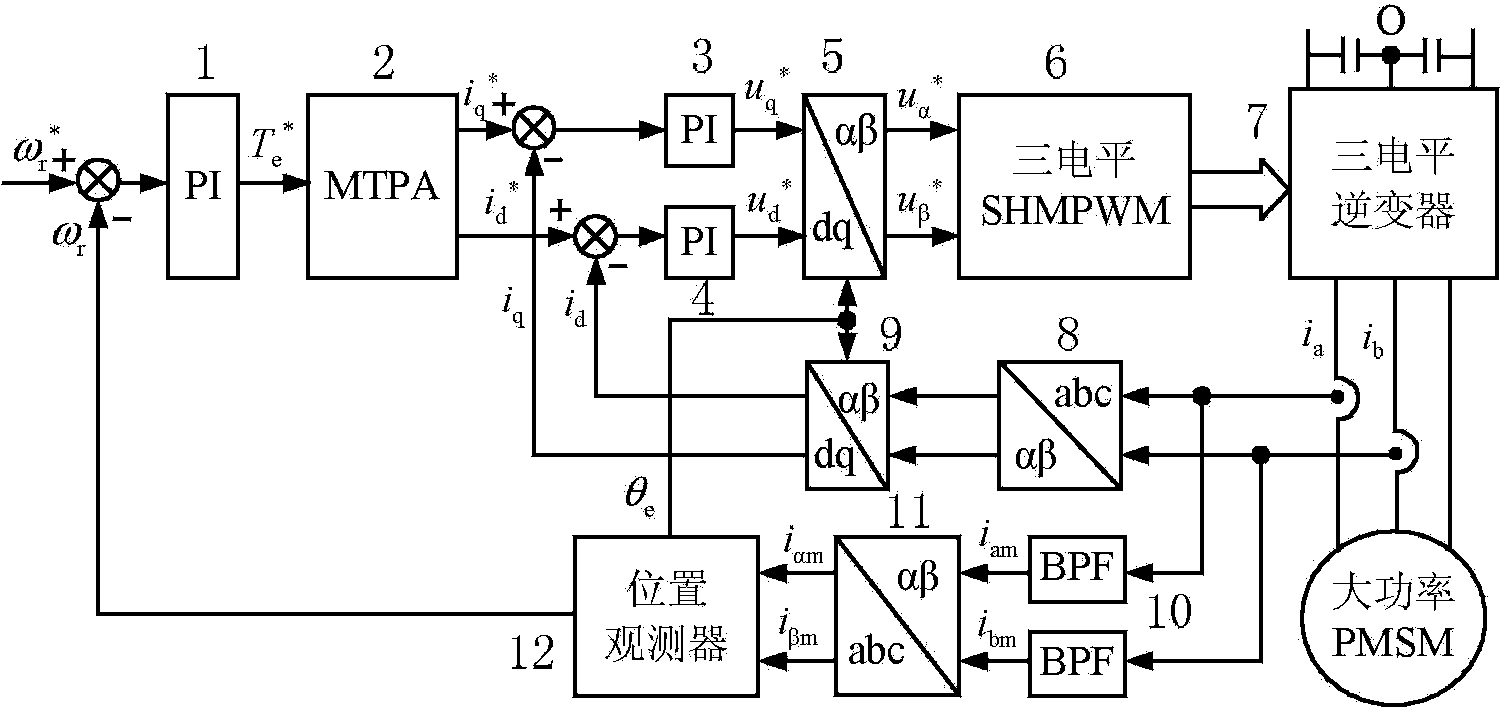
[0034] Specific implementation mode 1, refer to figure 1 and figure 2Specifically explain this embodiment, a high-power built-in permanent magnet synchronous motor position sensorless control system described in this embodiment, the system includes No. 1 PI calculation unit 1, used for angular velocity and rotor feedback angular velocity ω r Perform PI operation on the difference to get the given torque

[0035] MTPA maximum torque / amp unit 2 for the given torque on the Carry out the calculation of the maximum torque-current ratio, and obtain the d and q-axis current given values

[0036] The second PI calculation unit 3 is used to set the q-axis current value and q-axis current feedback value i q Perform PI operation on the difference to get the given value of q-axis voltage

[0037] No. 3 PI calculation unit 4, used to set the d-axis current value and the d-axis current feedback value i d Perform PI operation on the difference to get the d-axis voltage giv...

specific Embodiment approach 2

[0044] Specific Embodiment 2. A position sensorless control method of a high-power built-in permanent magnet synchronous motor position sensorless control system described in this specific embodiment, the method includes the following steps:

[0045] Step 1. Angular velocity and rotor feedback angular velocity ω r Make the difference, and perform PI operation on the difference to get the given torque

[0046] Step two, for the given torque Carry out MTPA maximum torque-current ratio calculation to obtain d and q-axis current given values

[0047] Step 3. Set value of q-axis current and q-axis current feedback value i q Perform PI operation on the difference to get the given value of q-axis voltage Given value for d-axis current and the d-axis current feedback value i d Perform PI operation on the difference to get the d-axis voltage given value

[0048] Step 4, set the q-axis voltage to a given value d-axis voltage given value and rotor position informat...

specific Embodiment approach 3

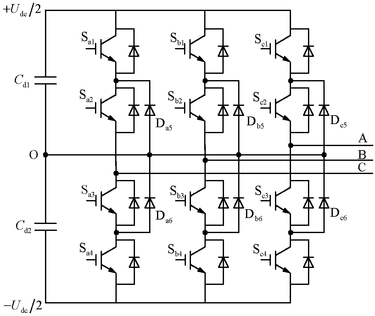
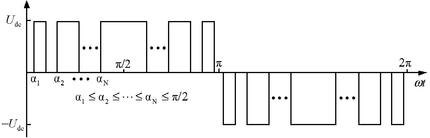
[0055] Specific implementation mode three, refer to image 3 and Figure 4 Describe this embodiment in detail. This embodiment is a further description of the position sensorless control method for a high-power built-in permanent magnet synchronous motor described in the second specific embodiment. In this embodiment, according to the α-axis given voltage and beta axis given voltage Obtain the modulation ratio, carry out the three-level SHMPWM operation, and then generate the process of the pulse width signal of the power device and the step 6 according to the power device pulse width signal through the three-level inverter unit output with constant amplitude, The mth harmonic voltage vector u with a phase difference of 120° am , u bm , u cm The acquisition process of the three-phase three-level voltage signal is as follows:

[0056] Step 11, assuming that there are N conversion angles in [0, π / 2] cycles, a i (i=1,2,3,...,N) is the conversion angle, according to the F...


PUM


Abstract

The invention provides a high-power built-in permanent magnet synchronous motor position-sensorless control system and a control method, and belongs to the field of motor control. The control system solves the problem that when a traditional high-power built-in permanent magnet synchronous motor system works at a low switch frequency, low-order harmonic content increases, and meets the requirements that low-order harmonic waves are weakened and meanwhile, rotating voltage vector control with constant amplitude values is produced. An SHMPWM technique is adopted, it is guaranteed that on a low-switch-frequency work condition, harmonic waves of a high-power permanent magnet synchronous motor system are inhibited, constraint conditions of SHMPWM non-linear transcendental equation sets are increased, and three-phase specific harmonic wave content signals with constant amplitude values and 120-degree phase angle differences are extracted from the weakened harmonic wave content to be used for estimation of a rotor position; specific harmonic currents are obtained through a band-pass filter; by means of a position observer, the estimated rotation speed and the rotor position of a permanent magnet synchronous motor are obtained, and position-sensorless rotation speed closed loop vector control of a motor is achieved. The control system and the control method are suitable for control of the motor.

Description

technical field [0001] The invention belongs to the field of motor control. Background technique [0002] Due to its high-efficiency and energy-saving design concept, the high-power permanent built-in magnetic synchronous motor drive system has broad application prospects in high-power electric drive systems such as civil electric vehicles, electric drive armored vehicles, and high-speed rail. an important research topic. [0003] In order to realize the high-performance control of the permanent magnet synchronous motor, the rotor position and speed information of the motor must be obtained, which is usually obtained through mechanical sensors such as encoders or resolvers. However, the installation of mechanical sensors brings problems such as increased system cost, reduced reliability, increased size, and reduced anti-interference ability. In order to broaden the application range of permanent magnet synchronous motors, it has been a research hotspot in the field of high...

Claims


Application Information

Patent Timeline
IPC IPC(8): H02P21/13
Inventor 于艳君柴凤程树康高立骁
Owner HARBIN INST OF TECH
Why Eureka
Try Eureka