
Femtosecond laser device based on single cladding neodymium optical fibers and ring cavity and manufacturing method

A femtosecond laser and single-clad technology, which is applied in lasers, laser components, phonon exciters, etc., can solve the problems of low light-to-light conversion efficiency, large fusion loss, and complex structure

Active Publication Date: 2014-07-23
PEKING UNIV
View PDF5 Cites 11 Cited by
  • Summary
  • Abstract
  • Description
  • Claims
  • Application Information

AI Technical Summary

Problems solved by technology

[0004] At present, the fiber femtosecond laser with a mode-locked central wavelength between 900-950nm has two main manufacturing methods. The first type of linear cavity outputs ultrashort pulses of 900-950nm. From the current international published papers, Dispersion elements must be added in the cavity to balance the dispersion, which has a certain limit on the single pulse energy, and it is difficult to exceed 0.5nJ; the second type is the latest research using W-type double-clad neodymium-doped fiber as the gain fiber in the ring cavity. The cross-sectional refractive index distribution is W-type, that is, core>outer cladding>inner cladding, although the neodymium-doped fiber with this structure can effectively suppress the four-level radiation at 1064nm at room temperature, thereby improving the wavelength between 900-950nm Three-level radiation, but its fusion loss with ordinary single-mode fiber or other double-clad fiber is large, resulting in low light-to-light conversion efficiency, less than 1%.
[0005] In short, the existing fiber femtosecond lasers in the 900-950nm band have technical defects of high cost, complex structure, low light-to-light conversion efficiency, and low femtosecond pulse energy

Method used


Image

  • Femtosecond laser device based on single cladding neodymium optical fibers and ring cavity and manufacturing method
  • Femtosecond laser device based on single cladding neodymium optical fibers and ring cavity and manufacturing method
  • Femtosecond laser device based on single cladding neodymium optical fibers and ring cavity and manufacturing method

Examples


Embodiment 1

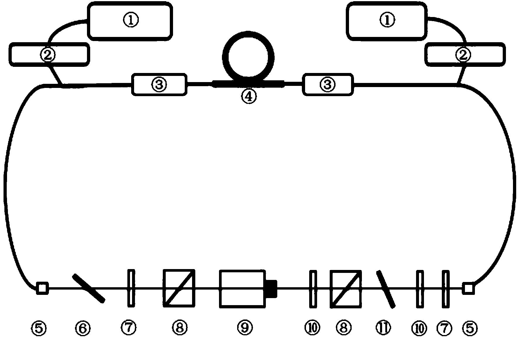
[0034] figure 1 It is a structural schematic diagram of a femtosecond laser based on a single-clad neodymium fiber and a ring cavity of a preferred embodiment of the present invention; in this embodiment, the femtosecond laser based on a single-clad neodymium-doped fiber and a ring cavity Laser, the femtosecond laser includes a cavity part and a spatial optical path part; the cavity part includes an 808nm single-mode semiconductor optical pump 1, an 808nm fiber-optic single-mode isolator 2, an 808 / 920nm wavelength division multiplexer 3, Single-clad neodymium-doped gain fiber 4, 920nm fiber collimator 5; the spatial optical path part includes a low-pass dichroic mirror 6, a 920nm1 / 4 wave plate 7, a 920nm polarization beam splitting prism 8, a 920nm Faraday rotator 9, 920nm 1 / 2 wave plate 10, birefringence filter 11; the 808nm single-mode semiconductor optical pump 1, the 808nm fiber-optic single-mode isolator 2, and the 808 / 920nm wavelength division multiplexer 3 are welded to...

Embodiment 2

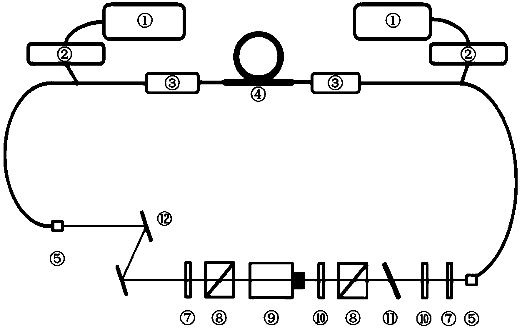
[0045] figure 2 It is a structural schematic diagram of a femtosecond laser based on a single-clad neodymium fiber and a ring cavity according to another preferred embodiment of the present invention; compared with Embodiment 1, this embodiment adds an optical device dispersion compensation grating pair 12, Located between the 920nm fiber collimator (5) of the first cavity and the 920nm1 / 4 wave plate (7) of the spatial optical path part, the low-pass dichroic mirror (6) is connected from the spatial optical path part remove. The dispersion compensation grating pair 12 is a reflective grating or a transmissive grating. The cavity part of this embodiment is the same as that of this embodiment, and the manufacturing method of this embodiment is the same as that of Embodiment 1, which will not be repeated here.

Embodiment 3

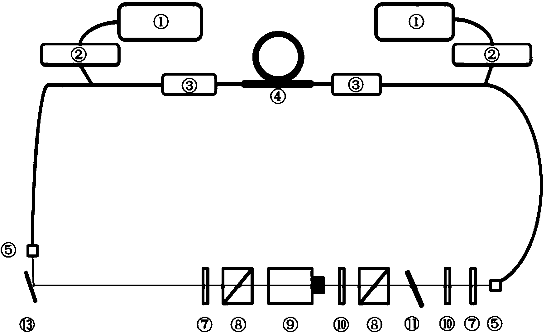
[0047] image 3 It is a structural schematic diagram of a femtosecond laser based on a single-clad neodymium fiber and a ring cavity according to another preferred embodiment of the present invention; compared with Embodiment 1, this embodiment adds an optical device filter grating 13, which is located at the Between the 920nm fiber collimator (5) of cavity 1 and the 920nm1 / 4 wave plate (7) of the spatial optical path part, the low-pass dichroic mirror (6) is removed from the spatial optical path part. The filter grating 13 is a reflective grating or a transmissive grating. The cavity part of this embodiment is the same as that of this embodiment, and the manufacturing method of this embodiment is the same as that of Embodiment 1, which will not be repeated here.

[0048] A femtosecond laser based on a single-clad neodymium fiber and a ring cavity of the present invention uses 808nm single-mode semiconductor optical pumping as an excitation light source to ensure sufficient h...


PUM


Abstract

The invention discloses a femtosecond laser device based on single cladding neodymium optical fibers and a ring cavity and a manufacturing method. The femtosecond laser device comprises a cavity part and a space optical path part, wherein the cavity part comprises 808 nm single mode semiconductor optical pumps (1), 808 nm optical fiber type single mode isolators (2), 808 / 920 nm wavelength division multiplexers (3), a single cladding neodymium-doped gain optical fiber (4) and 920 nm optical fiber collimators (5); the space optical path part comprises a low-pass dichroscope (6), 920 nm 1 / 4 wave plates (7), 920 nm polarization beam splitter prisms (8), a 920 nm Faraday optical rotation device (9), 920 nm 1 / 2 wave plates (10) and a birefringence filtering piece (11). Mode locking potential of the neodymium-doped optical fiber is explored between 900 nm and 920 nm, on the premise that single pulse energy is guaranteed, light-light conversion efficiency is improved, and meanwhile the laser device provides a better light source facilitating integration for an integrated two-photon fluorescence microscope.

Description

technical field [0001] The invention relates to the technical field of optical fiber femtosecond lasers, and more specifically relates to a femtosecond laser based on a single-clad neodymium optical fiber and a ring cavity and a manufacturing method thereof. Background technique [0002] Fiber femtosecond laser is one of the typical femtosecond laser technology. Femtosecond laser technology is an application technology developed rapidly on the basis of quantum optics and nonlinear optics in recent years. It is defined as an ultrafast laser pulse with a pulse width ranging from several femtoseconds to hundreds of femtoseconds, of which 1fs =10-15s. The new two-photon microscope needs to use a femtosecond laser as an excitation light source to be able to use the two-photon effect to excite biological fluorescent proteins for imaging. In this subfield, the conventional approach is to use Ti:Sapphire lasers as light sources, which have the advantages of reliable stability and ...

Claims


Application Information

Patent Timeline
Patent Type & Authority Applications(China)
IPC IPC(8): H01S3/067H01S3/08H01S3/101
Inventor 高翔王爱民陈冰影张健张志刚
Owner PEKING UNIV
Learn More