Converter valve assembly and valve tower using the converter valve assembly

A converter valve and component technology, applied in the direction of semiconductor/solid-state device parts, electrical components, electro-solid devices, etc., can solve the inconvenience of valve tower installation and maintenance, valve tower installation and maintenance operations, various units and water cooling systems. Discrete layout structure, etc., to achieve the effect of convenient and quick installation and maintenance, expansion of installation and maintenance space, and convenient installation and maintenance

Active Publication Date: 2017-03-01
XJ ELECTRIC
View PDF10 Cites 0 Cited by
  • Summary
  • Abstract
  • Description
  • Claims
  • Application Information

AI Technical Summary

Problems solved by technology

[0003] At present, the flexible DC transmission valve towers at home and abroad are all in the research and development stage. The valve tower adopts a supporting structure and a suspended structure. The valve tower is composed of multi-layer converter valve components. The arrangement is such as a thyristor converter valve module disclosed in Chinese patent document CN101719719B. A thyristor converter valve module is equivalent to a layer of converter valve assemblies. The thyristor converter valve module includes two symmetrically arranged valve sections, each The valve section also includes a saturable reactor component, a thyristor unit, a DC voltage equalizing resistor unit, an energy harvesting resistor unit, a damping resistor unit, a damping capacitor unit, a gate unit and a water cooling system, in which the thyristor unit, the DC voltage equalizing resistor unit, the energy harvesting The resistance unit, the damping resistance unit, the damping capacitance unit and the gate unit are fixed on the same frame to form a thyristor-level component. The saturable reactor is a separate component. The thyristor unit is composed of several thyristors and their accessories in series. Both sides of each thyristor are connected with a radiator and correspond to a damping resistor, damping capacitor, DC averaging resistance, energy-taking resistor and gate circuit. In terms of layout: the thyristor unit is the center, and gates are arranged on both sides of the thyristor unit. Pole unit, damping resistance and damping capacitor, thyristor-level components and saturated reactor components are connected in series to form a valve section, so each unit and water-cooling system in this thyristor converter valve module are relatively independently arranged on the frame, each unit and water-cooling The layout of the system is discrete, which makes the installation and maintenance of the valve tower extremely inconvenient
[0004] The Chinese patent document with the application number 201310239581.X discloses an IGBT power unit and a sub-module for flexible direct current transmission. The sub-module includes a capacitor, a busbar assembly and an IGBT module. The capacitor is fixed on the rear side of two supporting rails , There is a plate radiator between the IGBT module and its control circuit. Each IGBT module is equipped with a composite busbar connected to the capacitor. There are two IGBT modules and they are arranged between the two plate radiators. The top of the plate radiator is connected through a U-shaped water pipe. The IGBT power module, the thyristor crimping unit and the bypass switch are installed on the same fixed base. The fixed base is fixed on the front side of the two supporting rails. The main busbar is located on the The side of the fixed base facing away from the capacitor, the IGBT power module and the thyristor crimping unit connect the components of the main circuit through two composite busbars and the main busbar, so that the sub-module forms an integral module structure, but the existing technology There is still no reasonable layout of reversing valve components to match the sub-modules, so the existing valve tower still has the problem of inconvenient installation and maintenance

Method used


Image

  • Converter valve assembly and valve tower using the converter valve assembly
  • Converter valve assembly and valve tower using the converter valve assembly
  • Converter valve assembly and valve tower using the converter valve assembly

Examples


Embodiment Construction

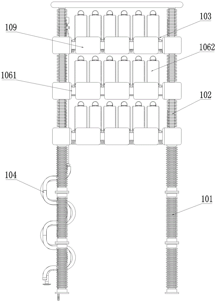
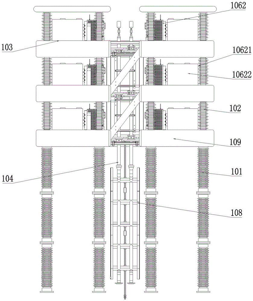
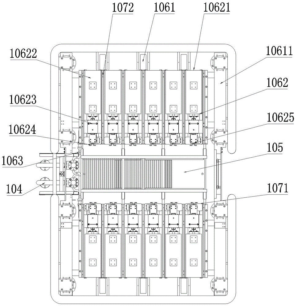
[0033] Embodiment 1 of the valve tower in the present invention: as Figure 1 to Figure 8As shown, the valve tower is a new type of flexible direct current transmission supporting valve tower. In this embodiment, the valve tower is a single tower structure. Water pipe 104, each valve group layer 103 is composed of two diverter valve assemblies arranged symmetrically front and back and an inspection platform 105 installed between them, each diverter valve assembly consists of a frame 1061 and submodules 1062 assembled on it, The branch water pipe 1063 is composed of five sub-modules 1062, which are arranged on the frame 1061 from left to right to form a valve section. The side of the mechanism close to the maintenance platform 105 is the drawing opening 1071 for the sub-module 1062 to enter and exit. The drawing openings 1071 of each guide mechanism are on the same side in the front and rear direction on the frame 1061, and are flush with each other on the left and right; The ...


PUM


Abstract

The invention discloses a converter valve assembly and a valve tower using the converter valve assembly. More than two sub-modules in the converter valve assembly are sequentially arranged on the frame to form a valve section, and each sub-module passes through a corresponding The guiding mechanism is assembled on the frame along the column direction of the valve section. The drawing openings of each guiding mechanism are on the same side in the front and rear direction on the frame. One end of each sub-module is the plug end corresponding to the drawing opening. The plug end is set at the tail end of the sub-module, and the branch water pipe is set close to the pull-out opening corresponding to the cooling device of the sub-module. During the maintenance and installation of the valve tower, the plug end of each sub-module can pass through the pull-out opening Guide and assemble on the frame from the same side of the guide mechanism, so that the cooling device at the end of the sub-module will be on the same side of the entire valve section, so that the operator can complete the sub-module on the frame at the side where the pull-out opening of the valve section is located The installation on the board makes the converter valve assembly convenient and quick to install and maintain.

Description

technical field [0001] The invention relates to a converter valve assembly and a valve tower using the converter valve assembly. Background technique [0002] Flexible DC transmission is a new generation of DC transmission technology with the voltage source converter as the core. Compared with AC transmission and conventional DC transmission, flexible DC transmission can flexibly adjust the voltage of the AC system while transmitting energy. Therefore, flexible DC Power transmission has obvious advantages such as good controllability, flexible operation mode, and many applicable occasions. Therefore, under the new form of current power grid construction that is increasingly difficult and renewable energy, distributed power, and grid intelligent technologies are rapidly developing, flexible direct current transmission technology It provides a new way to make up for the shortcomings of traditional high-voltage AC-DC transmission technology. [0003] At present, the flexible D...

Claims


Application Information

Patent Timeline
Patent Type & Authority Patents(China)
IPC IPC(8): H02M1/00H02J1/00H01L23/473
CPCH02M1/00H05K7/14339
Inventor 姚为正张建张承朱新华李申肖晋姚志国毛志云
Owner XJ ELECTRIC
Why Eureka
Try Eureka