Digital image filter circuit design method based on FPGA evolutionary learning
A filter circuit and design method technology, applied in the field of image processing, can solve problems such as obvious noise, difficult circuit, no consideration of circuit competition and risk, etc., to achieve good visual effect and improved performance
- Summary
- Abstract
- Description
- Claims
- Application Information
AI Technical Summary
Problems solved by technology
Method used
Image
Examples
Embodiment 1
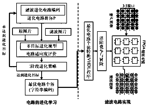
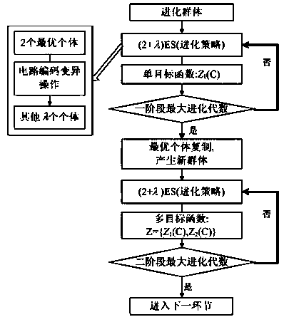
[0037] Embodiment one: see figure 1 As shown, a digital image filter circuit design method based on FPGA evolutionary learning, including the evolutionary learning stage and the filter circuit hardware implementation stage, the specific steps are as follows:
[0038] (1) Gene expression is used to encode circuits, and each evolutionary circuit has 9 inputs (3 3 filtering window pixels), the circuit is composed of bit logic function modules, and there are 29 function modules in total, as shown in Table 1:
[0039] Table 1 Definition of circuit function characters
[0040]
[0041] The evolutionary circuit is coded as a string expression, which is composed of function characters and terminal characters, and the terminal characters are denoted as ,Right now ~ , representing the 9 inputs of the circuit, the function character is denoted as , namely in Table 1 ~ . A string expression represents a circuit. The expression structure is divided into a head and a tail....
Embodiment 2
[0059] Embodiment 2: Gaussian white noise with a variance of 0.04, 0.06 and 0.08 is loaded to 13 standard pictures for learning, the obtained circuit is tested on the sailboat picture, and the peak signal-to-noise ratio PSNR and The minimum mean square error MSE is shown in Table 2:
[0060] Table 2 Peak Signal-to-Noise Ratio / Mean Square Error (PSNR / MSE) of image filtering with different concentrations of Gaussian noise
[0061]
[0062] see Figure 4 as shown, Figure 4 (a) is Gaussian noise (D=0.08) sailboat image, Figure 4 (b) is an evolutionary filter (single target) image, Figure 4 (c) is an evolutionary filtering (multi-objective) image, Figure 4 (d) is the frost filtered image, Figure 4 (e) for Lee filtering, Figure 4 (h) Filtering images for wavelets.
[0063] From Table 2 and Figure 4 It can be seen that under Gaussian noise, the difference between multi-objective evolution and other methods is small, but the color is more vivid. The average filterin...
Embodiment 3
[0064] Embodiment 3: load salt and pepper noise with variances of 0.12, 0.16 and 0.2 to 13 standard pictures for learning, and the obtained circuit is tested on the lenna picture, and the peak signal-to-noise ratio (PSNR) and minimum average value of the circuit for the salt and pepper noise and the lenna picture are obtained. The variance MSE is shown in Table 3:
[0065] Table 3 Peak Signal-to-Noise Ratio / Mean Square Error (PSNR / MSE) of Image Filtering for Each Concentration of Salt and Pepper Noise
[0066]
[0067] see Figure 5 as shown, Figure 5 (a) is the salt and pepper noise (D=0.2) lenna image, Figure 5 (b) is an evolutionary filter (single target) image, Figure 5 (c) is an evolutionary filtering (multi-objective) image, Figure 5 (d) is the frost filtered image, Figure 5 (f) is kuan filtered image, 5(g) is 5 5 mean filtered image.
[0068] From Table 3 and Figure 5 It can be seen that under salt and pepper noise, the PSNR of the filter circuit is sm...
PUM
 Abstract
Description
Claims
Application Information
 - R&D
- Intellectual Property
- Life Sciences
- Materials
- Tech Scout
- Unparalleled Data Quality
- Higher Quality Content
- 60% Fewer Hallucinations
Browse by: Latest US Patents, China's latest patents, Technical Efficacy Thesaurus, Application Domain, Technology Topic, Popular Technical Reports.
© 2025 PatSnap. All rights reserved.Legal|Privacy policy|Modern Slavery Act Transparency Statement|Sitemap|About US| Contact US: help@patsnap.com


