Medium pressure high temperature steam control system

A high-temperature steam and control system technology, applied in pipeline systems, lighting and heating equipment, tubular components, etc., can solve the problems of increased production costs and expensive natural gas, and achieve low cost, low price, and avoid smog effects

Inactive Publication Date: 2016-11-30
ZHEJIANG JINGBAO MACHINERY
View PDF5 Cites 0 Cited by
  • Summary
  • Abstract
  • Description
  • Claims
  • Application Information

AI Technical Summary

Problems solved by technology

Therefore, some enterprises started to burn natural gas, but the price of natural gas was high, and the production cost was greatly increased, so it could not be popularized in the market

Method used


Image

  • Medium pressure high temperature steam control system
  • Medium pressure high temperature steam control system
  • Medium pressure high temperature steam control system

Examples


Embodiment 1

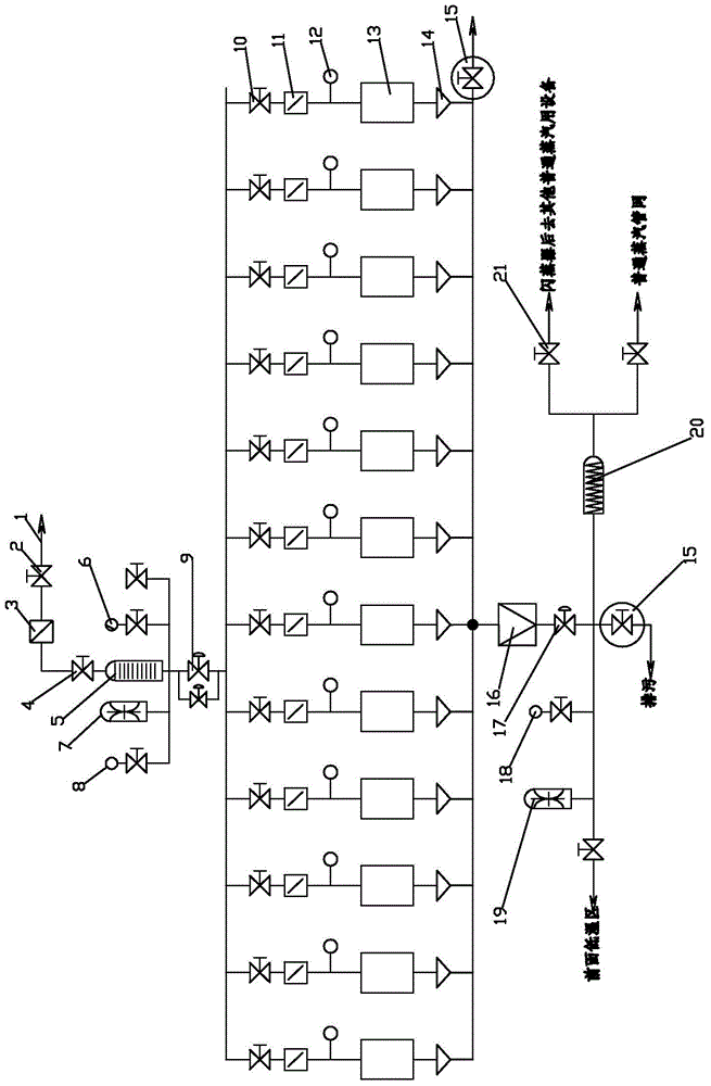
[0032] Such as figure 1 As shown, the medium-pressure high-temperature steam control system of the present invention includes a medium-pressure high-temperature pipe network 1, and the medium-pressure high-temperature pipe network 1 is sequentially installed with a first manual valve 2, a filter screen 3, a second manual valve 4 and a measuring instrument 5 , the first safety valve 7 and the thermometer 6 are respectively installed on both sides of the meter 5, the first pressure gauge 8 is installed on one side of the first safety valve 7, the automatic valve 9 is installed under the meter 5, the automatic valve 9 There are two parallel ones. Several heat exchange components are installed under the automatic valve 9. A pressure reducing valve 16 and an automatic intelligent valve 17 are installed in sequence under the heat exchange components. A third pressure gauge is respectively installed on both sides of the automatic intelligent valve 17. 18 and steam trap 20, a second s...

Embodiment 2

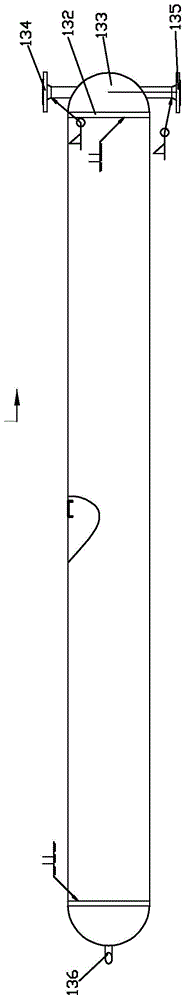
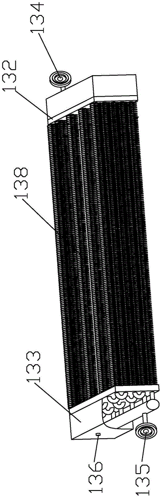
[0038] Such as Figure 4 As shown, several heat-conducting tube-connected heat exchanger fins 131 in this embodiment 2 are installed in parallel, the inlet flange 134, outlet flange 135 and water outlet 136 are installed on the same head 133, and the inlet flange 134 is located at the outlet Above the flange 135 , the water outlet 136 is installed at the bottom of the sealing head 133 .

[0039] Other structures and connection methods of Embodiment 2 are the same as those of Embodiment 1, and will not be repeated here.

Embodiment 3

[0041] Such as Figure 5 As shown, the medium-pressure high-temperature steam heating heat exchanger 13 in Embodiment 3 is the first horizontal type, and several heat-conducting tube-connected heat exchanger fins 131 are arranged horizontally and left and right, and the inlet flange 134, outlet flange 135 and water outlet 136 is installed on the same head 133, and the inlet flange 134 is located above the outlet flange 135, and the water outlet 136 is installed at the bottom of the head 133.

[0042] Other structures and connection methods of Embodiment 3 are the same as those of Embodiment 1, and will not be repeated here.


PUM


Abstract

The invention relates to a medium-pressure high-temperature steam control system, comprising a medium-pressure and high-temperature pipe network, wherein a first manual valve, a filter screen, a second manual valve and a meter are installed in sequence on the medium-pressure and high-temperature pipe network. A first safety valve and a temperature gauge are installed, a first pressure gauge is installed on one side of the first safety valve, an automatic valve is installed below the measuring instrument, and a number of heat exchange components are installed below the automatic valve. A pressure reducing valve and an automatic intelligent valve are installed, a third pressure gauge and a steam trap are installed on both sides of the automatic intelligent valve, a second safety valve is installed on one side of the third pressure gauge, and one side of the second safety valve is connected with a In the low temperature zone, one side of the trap is connected with a flasher and a common steam pipe network. The invention meets the requirements of medium pressure and high temperature in industrial production, the generated waste water is applied to other equipment, and the waste gas is discharged in the low temperature area, so as to realize the comprehensive utilization of energy, and is suitable for application in the fields of tanning tenter machines, hot needle spinning and setting machines, etc. .

Description

technical field [0001] The invention relates to a steam control system, in particular to a medium-pressure high-temperature steam control system, which is applied in the fields of textile, printing and dyeing, rubber, tanning, wood processing, grain, oil and food processing, painting and baking paint, etc. Background technique [0002] At present, the direct consequence of the rapid development of industry is that the smog weather is getting more and more serious. Therefore, most areas resolutely resist the combustion of small boilers that use coal as raw material, so as to eliminate the source of smog weather. Therefore, some enterprises started to burn natural gas, but the price of natural gas was high, and the production cost was greatly increased, so it could not be popularized in the market. Steam is widely used in various fields of industrial production because of its low price and no adverse impact on the environment, such as textiles, printing and dyeing, rubber, lea...

Claims


Application Information

Patent Timeline
Patent Type & Authority Patents(China)
IPC IPC(8): F17D1/06F17D3/01F28D1/04F28F1/24
Inventor 陆宝夫陆伟峰虞卫兴陶家明方安兴高火林
Owner ZHEJIANG JINGBAO MACHINERY
Why Eureka
Try Eureka