Rotor wing dynamic test device

A dynamic test and rotor technology, applied in the field of aviation test platform, can solve the problems of high difficulty in attitude motion control, limited motion simulation ability, limited verification research, etc., and achieve the effect of compact structure

Inactive Publication Date: 2014-07-30
NANJING UNIV OF AERONAUTICS & ASTRONAUTICS
View PDF7 Cites 41 Cited by
  • Summary
  • Abstract
  • Description
  • Claims
  • Application Information

AI Technical Summary

Problems solved by technology

[0004] The flight simulation platform designed by using hydraulic actuators can simulate the three-direction rotational freedom movement of the helicopter body. During the simulation, the stroke is relatively small, decoupling is difficult, the difficulty of attitude motion control is relatively high, and the motion simulation capability is limited. In order to realize the motion simulation of a large stroke, the volume of the test equipment will be relatively large
[0005] When carrying out the dynamic maneuvering simulation experiment of the helicopter rotor, there are requirements from the motion simulation of a single degree of freedom, the coupling simulation of several motion degrees of freedom, and the coupling simulation of six degrees of freedom in space. The decoupling requirements for high-speed motion are relatively high. Due to the lack of test equipment that can simulate the impact of helicopter movement in the air on the rotor, it is necessary to use the real machine to carry out flight tests, which increases the research cost and risk, and limits the development of high-precision rotors. Verification research of advanced theoretical methods such as unsteady aerodynamics, flight mechanics and multi-body dynamics

Method used


Image

  • Rotor wing dynamic test device
  • Rotor wing dynamic test device
  • Rotor wing dynamic test device

Examples


Embodiment Construction

[0025] The present invention will be further described below in conjunction with accompanying drawing.

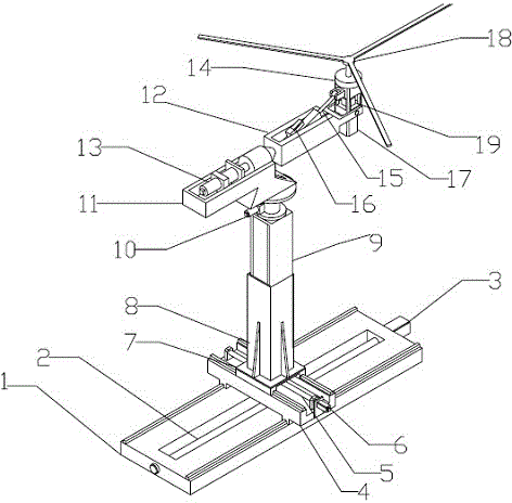
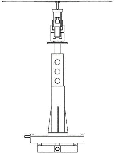
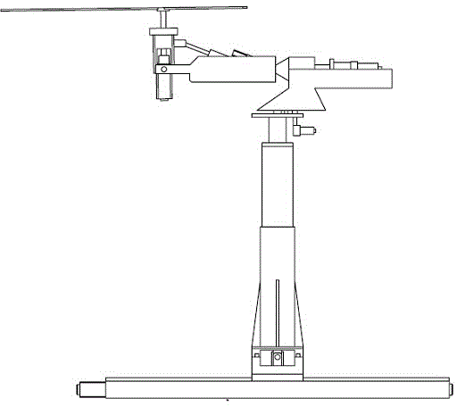
[0026] The perspective view of the present invention is as figure 1 As shown, the front view, side view and rear view are respectively as figure 2 , image 3 with Figure 4 shown.

[0027] When carrying out the test, the base plate 1 is fixed on the ground, and the longitudinal servo motor 3 on the base plate 1 transmits the power to the longitudinal slider 4 through the longitudinal screw 2, and the longitudinal slider 4 moves forward and backward along the guide rail in a straight line, thereby realizing the longitudinal linear motion simulation.

[0028] The lateral servo motor 6 installed on the longitudinal movement slider transmits the power to the lateral movement slider 7 through the lateral movement screw rod 5, and the lateral movement slider 7 moves linearly along the guide rail, thereby realizing the lateral linear motion simulation .

[0029] The power i...


PUM


Abstract

The invention provides a rotor wing dynamic test device which comprises a model rotor wing system, a pitching motion simulation mechanism, a rolling motion simulation mechanism, a course rotation simulation mechanism, an x-y-z axis horizontal moving device and a test accessory device. Seven independent control servo motors are used for the rotor wing dynamic test device and used for respectively driving longitudinal, lateral and transverse linear motions, pitching, rolling and course rotation motions and rotation of a model rotor wing. The seven servo motors are respectively provided with an independent control system, six-freedom-degree motion laws and the rotor wing rotating speed can be dynamically combined to be controlled under control of a central industrial personal computer, model test study on influences of dynamic maneuvering flight of helicopters on the aspects such as rotor wing pneumatic and flight mechanics and dynamics can be conducted, and motion combination tests among different degrees of freedom can be carried out according to needs.

Description

technical field [0001] The invention relates to the field of aviation test platforms, in particular to a rotor dynamic test device. Background technique [0002] The working environment of helicopter rotor blades is far more complicated than that of fixed-wing aircraft wings. Especially in dynamic maneuvering flight, the unsteady motion of the helicopter leads to lagging of the response of the rotor wake vortex, complex dynamic distortion of the geometry, and changes in the inflow of the paddle disc. distribution characteristics, and the inertial coupling caused by body motion is added to the rotor. At this time, the unsteady aerodynamic environment of the rotor will change significantly, and cause the rotor to produce more complex dynamic characteristics than the steady flight state, further increasing the aerodynamic and dynamic characteristics of the rotor. Difficulty in kinetic analysis. [0003] For the theoretical research of helicopter rotors in dynamic maneuveri...

Claims


Application Information

Patent Timeline
Patent Type & Authority Applications(China)
IPC IPC(8): G01M9/06
Inventor 杨卫东董凌华刘士明
Owner NANJING UNIV OF AERONAUTICS & ASTRONAUTICS
Why Eureka
Try Eureka